 |
|||
|
Page Title:
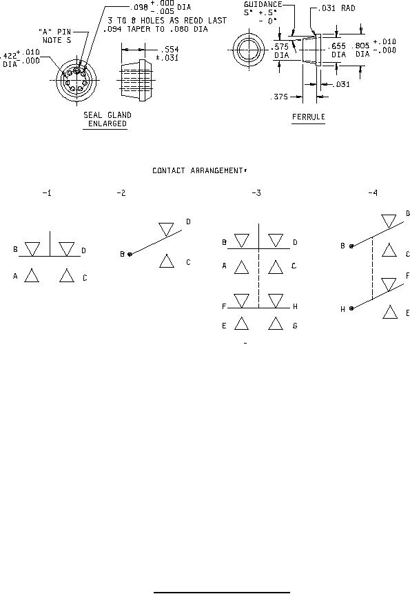
Figure 1. Dimensions and configuration - Cont'd |
|
||
| ||||||||||
|
|  MIL-S-8805/51D
Inches
mm
Inches
mm
Inches
mm
Inches
mm
.005
0.13
.193
4.90
.655
16.64
1.218
30.94
.010
0.25
.250
6.35
.734
18.64
1.250
31.75
.015
0.38
.375
9.53
.805
20.45
1.450
36.83
.031
0.79
.422
10.72
.843
21.41
1.563
39.70
.047
1.19
.554
14.07
.875
22.23
1.875
47.63
.080
2.03
.562
14.27
.937
23.80
2.500
63.50
.094
2.39
.575
14.61
1.031
26.19
3.094
78.59
.098
2.49
.625
15.88
1.125
28.58
NOTES:
1. Dimensions are in inches.
2. Metric equivalents are given for general information only.
3. Unless otherwise specified, tolerance is .015 (0.38 mm), except .005 (.127 mm) for ferrule and seal
gland.
4. The "A" pin shall be permanently indicated with a circle.
5. One hole on small end of gland shall be permanently marked with a circle, to be mounted on "A" pin.
6. The circuit and the terminal arrangement shall be marked on the switch case.
7. The dimensions of the electrical conduit coupling nut shall be in accordance with AN3054-8 or
equivalent. Alternative base metals and protective finishes, as approved by the qualifying activity, may
be used.
FIGURE 1. Dimensions and configuration - Continued
2
|
|
Privacy Statement - Press Release - Copyright Information. - Contact Us |
