 |
|||
|
Page Title:
Figure 1. Dimensions and configuration - Cont'd |
|
||
| ||||||||||
|
| 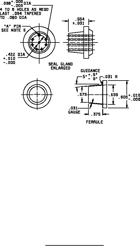 MIL-S-8805/53E
Inches
mm
Inches
mm
Inches
mm
Inches
mm
.0003
.01
.094
2.39
.500
12.70
1.125
28.58
.005
0.13
.098
2.49
.554
14.07
1.218
30.94
.010
0.25
.125
3.18
.562
14.27
1.25
31.75
.015
0.38
.193
4.90
.575
14.61
1.563
39.70
.031
0.79
.25
6.35
.609
15.47
1.781
45.24
.047
1.19
.31
7.87
.655
16.64
1.875
47.63
.070
1.78
.375
9.53
.805
20.45
2.50
63.50
.080
2.03
.422
10.72
.937
23.80
NOTES:
1. Dimensions are in inches.
2. Metric equivalents are given for general information only.
3. Unless otherwise specified, tolerances are .02 (0.51 mm) for two place decimals and .010 (0.25
mm) for three place decimals.
4. The "A" pin shall be permanently indicated with a circle.
5. One hole on small end of gland shall be permanently marked with a circle, to be mounted on "A" pin.
6. The circuit and the terminal arrangement shall be marked on the switch case.
7. The dimensions of the electrical conduit coupling nut shall be in accordance with AN3054-8 or
equivalent. Alternative base metals and protective finishes, as approved by the qualifying activity, may
be used.
FIGURE 1. Dimensions and configuration - Continued.
2
|
|
Privacy Statement - Press Release - Copyright Information. - Contact Us |
