 |
|||
|
Page Title:
Figure 1. Dimensions and configurations - Cont'd |
|
||
| ||||||||||
|
|  MIL-S-8805/85E
Max weight
A
B
Operating torque
PIN
with leads
Max
Max
(Inch-pounds)
(Pounds)
M8805/85-001
1.03
1.03
.47
1
M8805/85-002
1.30
1.53
.88
3
Inches
mm
Inches
mm
Inches
mm
Inches
mm
Inches
mm
0.005
0.13
0.062
1.57
0.248
6.30
0.620
15.75
2.000
50.80
0.010
0.25
0.080
2.03
0.250
6.35
0.765
19.43
72.000
1828.80
0.018
0.46
0.090
2.29
0.340
8.64
1.000
25.40
0.030
0.76
0.120
3.05
0.375
9.52
1.240
31.50
0.047
1.19
0.140
3.56
0.560
14.22
1.300
33.02
0.050
1.27
0.178
4.52
0.590
14.99
1.530
38.86
NOTES:
1. Dimensions are in inches. Metric equivalents are given for general information only.
2. Unless otherwise specified, tolerances are .03 (0.76 mm) for one place decimals, .015 (0.38 mm) for two
place decimals, and .010 (0.25 mm) for three place decimals.
3. Configuration optional provided specified dimensions are not exceeded.
4. Lead wire shall be marked at intervals of 3.5 inches (88.9 mm) maximum with switch circuit identification
number followed by wire gauge number (1-20). The marking shall be legible, permanent, and shall not impair
the wire characteristics.
FIGURE 1. Dimensions and configurations - Continued.
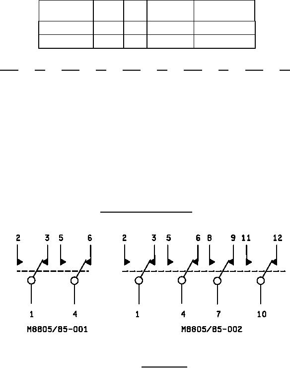
FIGURE 2. Circuit diagram.
REQUIREMENTS:
Dimensions and configuration: See figures 1 and 2.
2
|
|
Privacy Statement - Press Release - Copyright Information. - Contact Us |
