 |
|||
|
|
|||
| ||||||||||
|
|  MIL-T-21369C(OS)
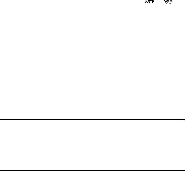
4.8.2.7.3 Cable assembly CA-802 (see 6.5). At a temperature between
and
and a
relative humidity between 45 and 95 percent, measure the insulation resistance between pins A and
B of the connector of Cable Assembly CA-802 using the insulation measuring device specified by
4.7n. Test potential shall not be applied for more than 5 seconds. The resistance measured shall
be 50 megohms or more.
4.8.2.8 Continuity test switch operation. With the test set energized, procedures 4.8.2.8a
through 4.8.28d shall be performed in sequence.
a. Set the TEST SELECTOR switch at 1.
b. If the HOME lamp is not lit, depress and hold the ADVANCE switch until the HOME
lamp lights.
c. Progressively connect and remove a jumper between the points listed by table VII, turning
the CONTINUITY TEST switch to the position indicated by the table. The green panel lamp
PL 14 shall light or be extinguished as indicated by table VII. Panel lamp PL 14 shall not be lit
in absence of a jumper.
d. Remove the jumper. Panel lamp PL 14 shall be extinguished.
TABLE VII. Location of jumper.
Position of
Panel Lamp P14
Continuity
Adapter Cables
Test Switch
Lit or Not Lit
Step
Connector
Across Pins
Lit
1
1
19-pin,
PI
P and S
Not Lit
2
P and S
2
19-pin,
PI
Lit
3
2
19-pin,
PI
R and T
Not Lit
4
3
19-pin,
P1
R and T
5
14-pin,
P2
Lit
3
Land M
4.8.2.9 Test circuits operation. With the test set energized, procedures 4.8.2.9a through 4.8.2.9f
shall be performed in sequence.
a. Set the TEST SELECTOR switch in position 1.
b. If the HOME lamp is not lit, depress and hold the ADVANCE SWITCH until the HOME
lamp lights.
c. Connect a jumper across pins A and B of the TEST STAND connector.
27
|
|
Privacy Statement - Press Release - Copyright Information. - Contact Us |