 |
|||
|
|
|||
| ||||||||||
|
|  MIL-T-22913C(OS)
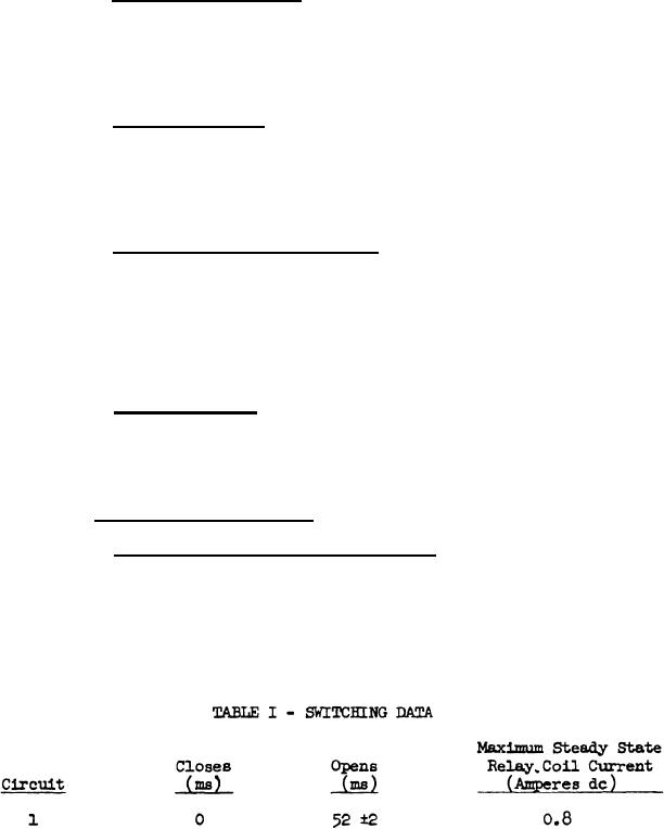
3.3.1.3.2 Switching functions. With the timer motor operating on an
input frequency of 400 Hz, and on the applicable input voltage specified
in 3.3.1.1(a), the timer shall perform the switching functions specified
in Tables I and II. Unless otherwise specified, all times listed in
Table I are with respect to the closure of circuit 1. For corrections
in time due to variations in frequency, see 4.5.4.3.2.
3.3.1.3.3 Contact ratings. Switches shall be capable of making and
breaking the load current specified in Table I for the circuit in which
they are used at a voltage of 26 volts dc plus or minus 10 percent and
in Table II for the circuit in which they are used at a voltage of 7 volts
plus or minus 10 percent, 400 Hz plus or minus 10 percent, and or 3 volts
dc plus or minus 10 percent.
3.3.1.3.4 Switch circuit voltage drop. Switch circuit voltage drop
shall not exceed:
(a) Two volts dc at the current specified in Table I when measured
at the connector terminals.
(b) One-half volt, 400 Hz at the current specified in Table II when
measured at the connector terminals.
3.3.1.3.5 Contact bounce. The duration of contact bounce occurring
in any circuit at switch closure shall not exceed one ms for circuits 1
through 5 inclusive and three ms for circuits 6 and 7. For purposes of
time measurement, a circuit shall be considered closed when the switch
contacts meet for the first time during each repeat-cycle.
3.3.1.4 Dielectric requirements
3.3.1.4.1 DC and potentiometer 155 circuits. The switches and the
O to 14 volt potentiometer 155 shall be capable of withstanding 500 volts
rms, 60 Hz between terminals P152-9 through P152-22 (inclusive) and the
timer chassis, with the motor and 90 volt potentiometer terminals, P152-1
through P152-7 (inclusive), grounded to the chassis. The test voltage
shall start at zero volts, be raised to 500 volts rms within 20 seconds,
and then maintained for one minute. No arcing or breakdown of insulation
shall occur.
6
|
|
Privacy Statement - Press Release - Copyright Information. - Contact Us |
