 |
|||
|
Page Title:
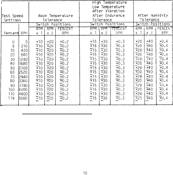
Table I. Digital Speed Indicator |
|
||
| ||||||||||
|
|  MIL-T-26219A
The output of the AN5547-2 four pole tachometer generator incorporated within
the test shall be connected to the Type E-30 tachometer indicator by properly
positioning the AN3226-1 switch. The RPM-PERCENT RPM switch shall be placed in
the RPM x 2 range position,
The test set shall be electrically energized and
the variable speed drive control operated to cause the Type E-30 tachometer
The test set shall be
indicator to register within its complete design range.
capable of driving the tachometer indicator undergoing test smoothly over the
Pointer oscillation shall not be encountered with the Type E-30
design range.
indicator when readings are taken at 1000, 2000, 3000, and 4000 rpm settings.
TABLE I
Digital Speed Indicator
4.6.3 Resistance load - output voltage. AN MS28054-2 two-pole tachometer
generator shall be attached to the mounting pad located on the control panel.
The generator shall be electrically connected to the "test generator input"
receptacle by means of adapter "A" shown on Figure 4.
The test shall be
electrically energized and the variable speed drive control rotated until the
digital indicator registers approximately 25 percent rpm. The resistance load
switch shall be rotated to the 20 ohm position and the voltage checked across
the generator ouput terminals A-B, B-C, and A-C, by means of the voltmeter and
associated selector switch provided on tne control panel.
The voltage
|
|
Privacy Statement - Press Release - Copyright Information. - Contact Us |