 |
|||
|
|
|||
| ||||||||||
|
|  MIL-T-6396E
4.6.6.1.5 Mounting axis. The tank shall be mounted in such a manner as to
simulate pitching in the actual aircraft. Special fixtures, such as baffles,
may also be tested, if applicable, by mounting in another position for a
portion of the test time.
4.6.6.1.6 Slosh rocking angle. The slosh rocking angle shall be 30 degrees
total, approximately 15 degrees on either side of the horizontal position.
4.6.6.2 Test duration.
Test duration and procedure shall be:
Vibrate for 25 hours at 16 to 20 slosh cycles per minute (cpm) or
a.
b. Vibrate for 25 hours at 10 to 16 slosh cpm with 15 hours of additional
slosh at 10 to 16 slosh cpm.
4.6.6.3 Type I tanks. The test tank, complete with all caps, vents, gages,
fittings, the nameplate, and other parts or accessories that will be mounted on
or in the aircraft, shall be mounted in the support jig and installed on the
vibrator and rocker assembly. In addition, all lines attached to the tank in
the actual aircraft installation shall be included. The minimum length of
these lines shall be that length in the actual aircraft installation from the
tank to the first support. (For testing of tanks which incorporate reticulated
foam or similar materials, see 4.6.6.5). The test specimen shall be filled
two-thirds-full with water and simultaneously slosh and vibration tested in
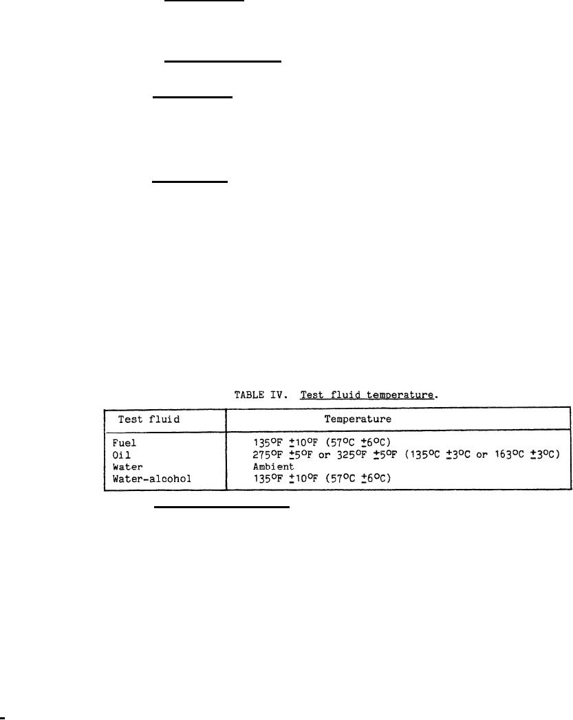
accordance with applicable conditions specified in 4.6.6.1. The temperature of
the test fluid shall be as specified in table IV. This test shall be conducted
with the test specimen subjected to a pressure equivalent to the maximum
operating pressure encountered in any prescribed flight conditions. At the
conclusion of this test, the test specimen shall be filled with the applicable
test fluid specified in 4.5.1, and thoroughly inspected for leakage or other
evidence of failure such as sagged panels or buckled plates which shall be
cause for rejection.
4.6.6.4 Types II and III tanks. The test tank, complete with all caps, vents$
gages, fittings, the nameplate, and other parts or accessories that will be
mounted on or in the aircraft, shall be mounted in the support jig arid
installed on the vibrator and rocker assembly. In addition, all lines attached
to the tank in the actual aircraft installation shall be included. The minimum
length of these lines shall be that length in the actual aircraft installation
from the tank to the first support. The interior or each compartment shall be
completely lined with brown paper and held in place with a suitable adhesive.
(For testing of tanks which incorporate reticulated foam or similar materials,
see 4.6.6.5.) The test specimen shall be filled two-third-full with the
applicable test fluid as specified in 4.5.1 containing a suitable dye. In
addition, for fuel tanks, twice the sump capacity of water shall be added to
the tank. For oil tanks employed in aircraft using an oil dilution system, 30
percent by volume of fluid conforming to TT-S-735, type III, shall be added to
16
|
|
Privacy Statement - Press Release - Copyright Information. - Contact Us |
