 |
|||
|
Page Title:
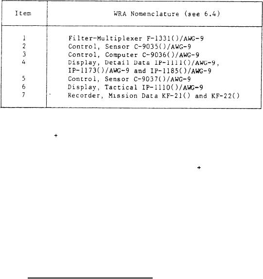
Table IV - WRAs Maintained at the C&D Test Station |
|
||
| ||||||||||
|
|  MIL-T-81783C(AS)
TABLE IV
WRAs MAINTAINED AT THE C&D TEST STATION
d. BIT Automatic Gain Control (AGC). Apply all enabling signals and
various levels of RF signals and measure the dc voltage on the BIT AGC line
1.0 percent.
to an accuracy of
e. AGC time constants. Apply all enabling signals and a square wave
modulated RF signal. Using an oscilloscope connected to the BIT AGC line
5 percent.
measure the various time constants to an accuracy of
f. Phase identification and phase timing. Apply Enable FMR signal
and with the counter, measure relative timing of Phase Identification,
A, B, C, and Phase Timing Signals.
g. Threshold control. Apply Mode Control logic and measure threshold
levels at test access provided.
h. Filter ringing test. Apply all enabling signals. Using a voltage
controlled oscillator, sweep through the entire filter bank and observe
the output video on an oscilloscope to check for proper ringing conditions,
3.4.1.2
Control, Sensor C-9035()/AWG-9. The C&D TS shall provide the
capability for performing the following tests on the sensor control
assembly:
Verify four position RDR EL BARS rotary switch operation.
a.
Verify four position RDR AZ SCAN rotary switch operation.
b.
Verify RDR AZ CNTR potentiometer operation.
c.
d.
Verify RDR EL CNTR potentiometer operation.
Verify four position IR EL BARS rotary switch operation.
e.
-9-
|
|
Privacy Statement - Press Release - Copyright Information. - Contact Us |
