 |
|||
|
|
|||
| ||||||||||
|
|  MIL-V-190698
c.
The valve handle shall be returned to the neutral position to
permit the buildup of the rated hydraulic pressure-in the
accumulator.
d.
The directional control valve
handle shall be quickly actuated
to permit reverse flow to the
check valve, The valve handle
shall be allowed to remain in
this position for at least three
seconds and then moved to the
original neutral position.
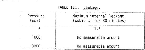
4.5.5 Leakage. This inspection shall be performed with the valve in the
horizontal position. Unless otherwise specified, this inspection shall be
0
conducted at a fluid temperature of 100 F. The valve shall be tested for
internal leakage by applying the pressure listed in table III for a minimum
period of 32 minutes each. The pressures shall be applied in the direction of
reverse flow and the valve poppet shall be mechanically unseated between
pressure applications. The leakage measurement period shall be a least 30
minutes in duration and shall begin two minutes after application of the
required pressure. The internal leakage shall not exceed the amounts stated
in table III. There shall be no measurable external leakage during this
inspection.
4.5.6 Operational inspection. Operational inspection shall consist of
two separate inspections: (1) checking time and (2) checking pressure. These
inspections shall be conducted within a temperature range of 70 to 120F.
When included as part of another inspection, the temperature specified for
that inspection shall apply.
4.5.6.1 Checking time. The valve poppet shall be mechanically actuated
to the full-open position against a static fluid head of 5 psi maximum; it
should then be allowed to check before the static head of fluid decreases to 1
psi minimum, The time between the release of the poppet and the cessation of
fluid flow shall be the checking time and shall not exceed 1.5 seconds.
4.5.6.2 Cracking pressure. Gradually increasing pressure shall be
applied in the free-flow direction beginning with zero pressure. Cracking
pressure is defined as that pressure at which fluid is bypassed through the
valve, and shall be not less than 2 psi or greater than 8 psi.
4.5.7 Pressure drop. This inspection shall be performed at a fluid
0
temperature of 100 F. The pressure drop through the check valve shall be
measured at a flow equal to the rated flow capacity. The fluid flow shall be
7
|
|
Privacy Statement - Press Release - Copyright Information. - Contact Us |