 |
|||
|
|
|||
| ||||||||||
|
|  MIL-V-24642(SH)
REQUIREMENTS
3.
3.1 First article. When specified (see 6.2.1), a sample shall be
subjected to first article inspection (see 4.3 and 6.3).
3.2 General description. This valve is intended for installation in
any position at the inlet of a steam driven turbine for the purpose of tripping
closed to stop steam flow and turbine operation upon electrical command from a
remote sensing system. The valve shall have a single seated disc which is
driven toward the seated position by spring force. A latch device which
opposes the spring force shall be engaged at all times regardless of the
handwheel or disc position until the 12 volt direct current (Vd.c.) solenoid is
energized. Energization of the solenoid will disengage the latch mechanism
allowing the valve to close under spring force. No damage shall occur to the
latch mechanism or seat if the maximum tangential force exerted on the rim of
the handwheel (see 3.4.10.3) is exceeded. A manual tripping device shall be
provided which will allow the valve, regardless of the position of the disc, to
be tripped manually in the event of a loss of electrical power. A handwheel
driven mechanism shall be incorporated to reset the valve after it has tripped
closed. Clockwise rotation of the handwheel to the stop position shall allow
manual engagement of the latch mechanism. Counterclockwise rotation shall then
lift the valve disc to the fully open position. The valve shall incorporate a
gland exhaust connection to prevent excess steam leakage past the stem without
resorting to packing.
3.3 Material. Valve body and bonnet material composition shall be 1-1/4
percent chromium and 1/2 percent molybdenum. Other material shall be as speci-
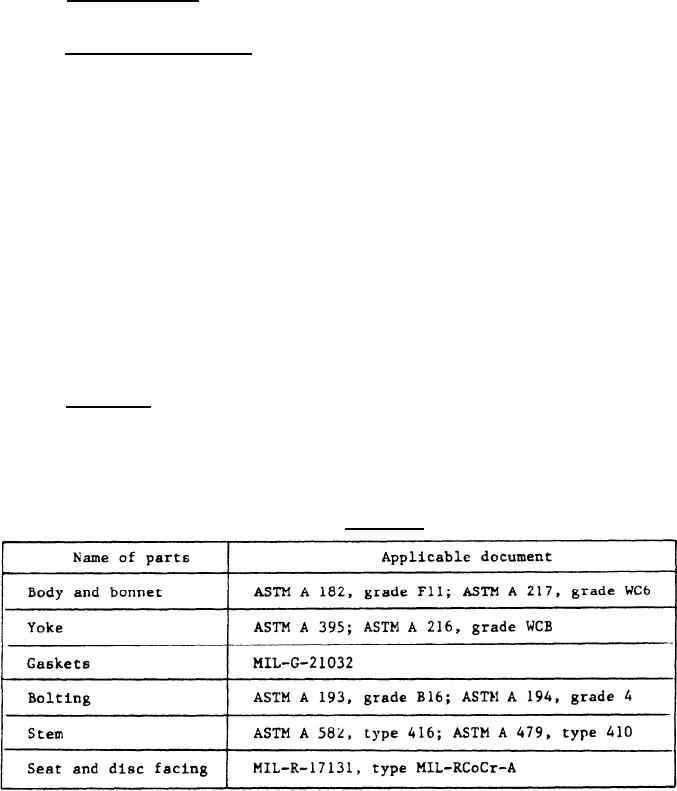
fied in table I. Material for parts not listed in table I shall be suitable
for the Intended pressures and temperatures, and selected to prevent galling,
seizing, or excessive wear on operating parts. Clearances shall prevent
interferences due to thermal expansion.
TABLE I.
Material.
|
|
Privacy Statement - Press Release - Copyright Information. - Contact Us |