 |
|||
|
|
|||
| ||||||||||
|
|  MIL-V-24642(SH)
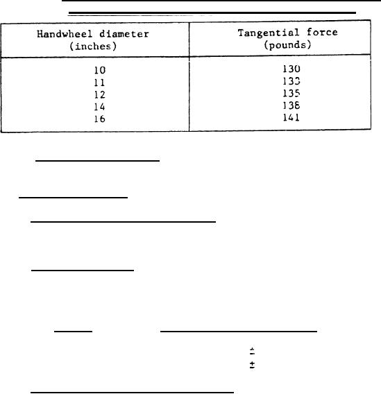
TABLE II.
Maximum allowable tangential force to operate valve
reset mechanism based on valve handwheel size. - Continued
Handwheels shall be secured to the valve
3.4. 10.4 Handwheel fastening.
stem with a locknut.
3.4.11 Body subassembly.
3.4.11.1 Pressure-temperature ratings. The design and pressure-
temperature rating for valves shall be 600 and 1,500 class in accordance with
ANSI B16.34.
3.4.11.2 End connections. The valves shall be furnished with 2-inch
nominal pipe size (rips) flanged ends in accordance with ANSI B16.5. Valves
shall be of a basic globe configuration with inline inlet and outlet ports.
Flange to flange distance shall be as shown below:
Rating
Flange to flange distance
13-3/4 inches
1/32 inch
600 class
1,500 class
16-1/2 inches
1/32 inch
3.4.11.3 Bonnet and bottom flange joints. Bonnet and bottom flange
(where applicable) shall be flanged for attachment to the body and shall be
located by body guiding (i.e., a close tolerance fit between machined diameters
on the body, bonnet and bottom flange) rather than depending on studs or bolts
for location. Spiral wound gaskets shall be fully retained, and the joints
shall have metal-to-metal take-up to provide controlled compression of the
gaskets. Joint design shall assure parallel alinement of the valve guiding
surfaces. Sufficient bolting area shall be provided to retain metal-to-metal
make-up. Flanges shall be secured by one of the following:
(a) Stud bolts threaded the entire length and fitted with a nut on
each end. Threads on bolts and nuts shall be a class 2 fit.
(b) Tap-end studs with interference fit at the tap end and a class 2
fit at the nut end. Interference fit shall be in accordance
with ANSI B1.12.
(c) Hex head cap screws in accordance with ANSI B18.2.1 or hexagon
socket head cap screws in accordance with ANSI B18.3.
7
|
|
Privacy Statement - Press Release - Copyright Information. - Contact Us |
