 |
|||
|
Page Title:
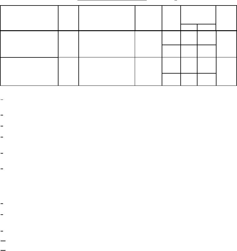
Table 1. Electrical performance characteristics-cont. |
|
||
| ||||||||||
|
|  MIL-M-38510/101H
TABLE I. Electrical performance characteristics Continued. 1/
Conditions
-55C ≤ TA ≤ +125C
Group A
Device
Limits
Unit
Test
Symbol
subgroups
type
see figure 4
unless otherwise specified
Min
Max
Vrms
7
01-06,
15
Noise (referred to input)
NI(BB)
VCC = 20 V, TA = +25C,
08
broadband
bandwidth = 5 kHz
07
25
Vpk
7
01,02,
40
Noise (referred to input)
NI(PC)
VCC = 20 V, TA = +25C,
04,06,
popcorn
bandwidth = 5 kHz
08
03,05,
80
07
1/
For devices marked the "Q" certification mark, the parameters listed herein maybe guaranteed if not tested
to the limits specified herein in accordance with the manufacturer's QM plan.
2/
Tests at common mode VCM = 0 V, VCM = -15 V, and VCM = +15 V.
3/
VIO(ADJ) is not performed on device type 02, case I only, or on device type 08 for either case G or P.
Continuous short circuit limits will be considerably less than the indicated test limits. Continuous IOS at TA ≤ +75C
4/
will cause TJ to exceed the maximum of +175C. For dual devices, IOS is measured one channel at a time.
5/
Value shown is for single devices (01, 03, 04) only. For dual devices (02, 05, 06, and 08) this limit is for single
devices.
6/
Note that gain is not specified at VIO(ADJ) extremes. Some gain reduction is usually seen at VIO(ADJ) extremes.
For closed loop applications (closed loop gain less than 1,000), the open loop tests (AVS) prescribed herein should
guaranteed a positive, reasonably linear, transfer characteristic. They do not, however, guarantee that the open loop
gain is linear, or even positive, over the operating range. If either of these requirements exist (positive open loop
gain or open loop gain linearity), they should be specified in the individual procurement document as additional
requirements.
RL = 10 kΩ only for device types 04 and 06.
7/
8/
For transient response tests, CF = 10 pF for device types 01, 02, 03, 04, 05, 06, and 08. Device type 07,
CF = 47 pF. CF includes the effects of stray capacitance.
Minimum limit for device 08 is 0.4 V/s at all temperatures.
9/
Minimum limits for device types 03 and 05 are 0.2 V/s at -55C and 0.3 V/s at both +25C and +125C.
10/
11/
Settling time is waived for method 5004, MIL-STD-883 except for device type 07.
13
|
|
Privacy Statement - Press Release - Copyright Information. - Contact Us |
