 |
|||
|
Page Title:
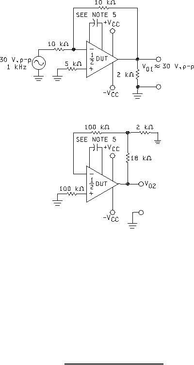
Figure 6. Test circuit for channel separation. |
|
||
| ||||||||||
|
|  MIL-M-38510/101H
Device types 02, 05, 06, and 08 only.
NOTES:
VCC = 20 V.
1.
2.
Measure: V02 (volts, p-p) at 1 kHz to accuracy of 0.1 mV or better.
3.
Channel separation (dB) referred to input of second channel = 20 log [V01 / (0.1 x V02) ].
All resistor tolerances ≤ 1 percent.
4.
5.
A 30 pF compensation capacitor is required for device types 05 and 06.
FIGURE 6. Test circuit for channel separation.
31
|
|
Privacy Statement - Press Release - Copyright Information. - Contact Us |
