 |
|||
|
Page Title:
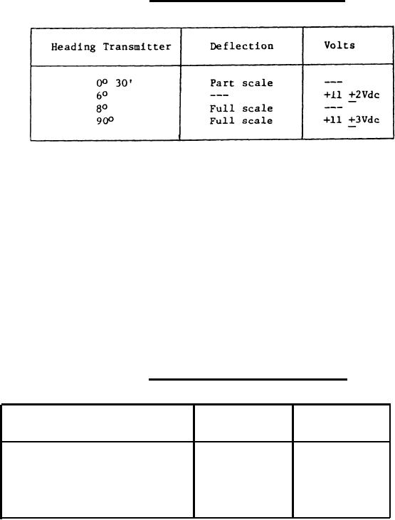
Table XVII. Sync Indicator Deflection Tests |
|
||
| ||||||||||
|
|  MIL-C-38418E(AS)
TABLE XVII.
Sync Indicator Deflection Tests
Position the azimuth detector to 90 and re-synchronize the
f.
system, leaving the displacement gyroscope heading transmitter at 90.
(1)
The sync indicator pointer must be centered within
1/16 inch.
The dc voltage from connector 2J2-18 to 2J2-17 must be
(2)
O 1Vdc.
Test for slaving amplifier (negative) output as follows:
g.
(1)
For the ASK-32/A24G-39 electronic control amplifier,
position the simulated azimuth detector to the following headings. The
sync indicator pointer on the controller must deflect toward negative (-)
to the proportion of scale noted, and the dc voltage must agree with the
following tabulation shown in table XVIII.
Sync Indicator Deflection Tests
TABLE XVIII.
volts
Deflection
Azimuth Detector Heading
---
Part scale
90 15'
---
93
-11 2Vdc -
---
94
Full scale
-11 3Vdc
180
Full scale
For the ASK-44/A24G electronic control amplifier,
(2)
position the simulated azimuth detector to the following headings. The
sync indicator pointer on the controller must reflect toward negative (-)
to the proportion of scale noted, and the dc voltage must agree with the
following tabulation shown in table XIX.
56
|
|
Privacy Statement - Press Release - Copyright Information. - Contact Us |
