 |
|||
|
Page Title:
Table XXI. Heading Set Control Resistance Measurements |
|
||
| ||||||||||
|
|  MIL-C-38418E(AS)
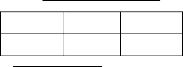
TABLE XXI.
Heading Set Control Resistance Measurements
Heading Set
2J3-14 to 2J3-15
Control Position
2J3-13 to 2J3-15
1 ohm max
1 megohm min
Depressed
1 ohm max
1 megohm min
Released
4.6.4.11 Malfunction Monitoring Circuit - The malfunction monitoring
circuit shall be tested as follows:
a.
Set the controls on the controller and the electronic control
amplifier as follows:
Mode switch to DG
Latitude control to O
Hemisphere switch to N
Compensation switch to OFF
b. Increase the input supply voltage (keeping all phases
balanced) until a malfunction is signaled; then repeat by increasing the
input supply voltage independently on each phase until a malfunction is
signaled (Note: do not exceed 138V line-to-nautral).
(1)
A malfunction shall be signaled as specified in
3.7.6.1, for a balanced input supply voltage in the range of 126.5 to
138V line-to-neutral.
(2)
A malfunction shall be signaled in accordance with
3.7.6.1, for a A, B, or C input supply voltage in the range of 126.5
to 138V line-to-neutral.
115 1V
(3)
Return
the
voltage to
input
supply
line-to-neutral.
The malfunction signals shall disappear.
voltage (keeping all phases
c,
Decrease the input supply
balanced) until a malfunction is signaled; then repeat by decreasing the
input supply voltage independently On each phase until a malfunction is
signaled.
63
|
|
Privacy Statement - Press Release - Copyright Information. - Contact Us |
