 |
|||
|
|
|||
| ||||||||||
|
|  MIL-C-50743(MU)
8 August 1973
b. With the 66. 5-kilohm resistor (item 1.5 of table I)
connected between J5-t and J5-j, the output at J1-d
shall be +0. 2 + O. 2 Vdc.
3.3.1.13 Malfunction 2 signal. With the digital type-B signals
(item 3.3 of table 1) applied as follows:
a. Logical one to J1-f, J1-h, and J1-AA
b. logical zero to J1-e, J1-g, and J1-z
c, Logical zero to J1-q,
momentary application of logical zero to J1-t shall cause the output at
J1-c to be +4.2 1.3 Vdc. Also, under the signal input conditions of
(a), (b), and (c), application of a logical one and a logical zero,
simultaneously, to J1-z and J1-AA, respectively, shall cause the output
at J1-c to be +0.2 O.2 Vdc.
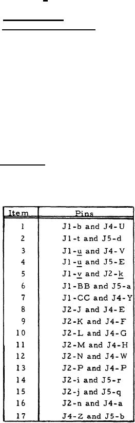
3.3.1.14 Continuity. With no signals or power applied, direct
continuity (resistance equal to or less than O.3 ohm) shall exist between
pins listed in table VII.
TABLE VII
CONTINUITY
14
|
|
Privacy Statement - Press Release - Copyright Information. - Contact Us |
