 |
|||
|
Page Title:
Table II. Physical requirements of Plastic support pole body. |
|
||
| ||||||||||
|
|  MIL-C-52765E(ME)
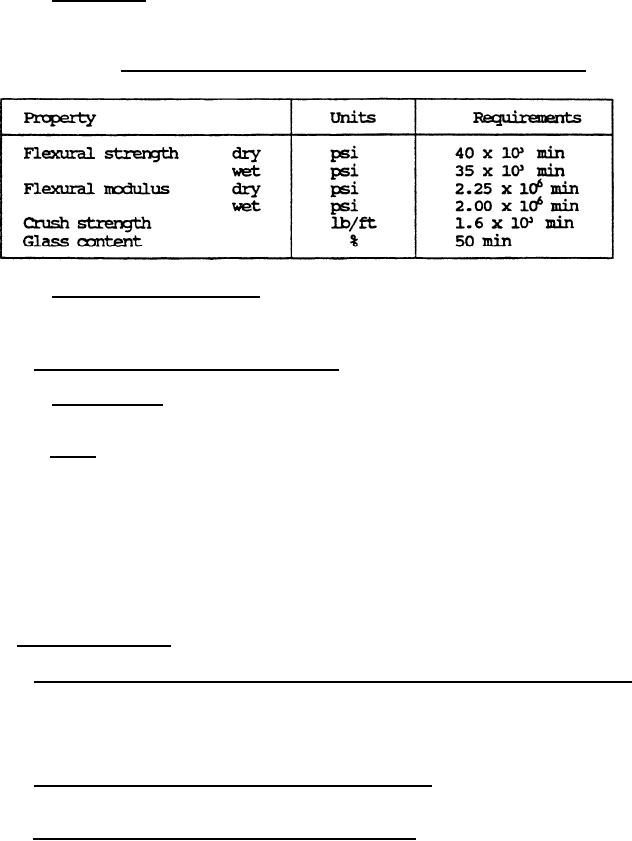
3.4.2.1 Pole body. The plastic pole body material shall be as specified in
the applicable drawings and shall meet the physical requirements as specified
in table II.
TABLE II. Physical requirements of Plastic support pole body.
3.4.2.2 Plastic pole assembly. Connector and end reinforcments, when
applicable, shall be permanetly attached to the pole body. the method of
attachmenbt shall meet the requirements specified herein.
3.4.3 Support pole, type I and type II.
3.4.3.1 Column load. When tested as specified in 4.5.2.1.3.1, a 4-section
pole shall support a 300-pound axial load for 60 seconds.
3.4.3.2 Drop. When tested as specified in 4.5.2.1.3.2, the support poles
shall sustain no damage which inhibits assembly or disassembly with a 1.568
OD/1.565 ID gauge. The type I support PolesShall show no slippage of the
sleeve into the pole body more than 0.25-inch. The type II supprt pies
shall shcw no evidence of fiberglass fibers exposed or protruding out of
resin, failure of the joint section, chips more than 0.25-inch deep, or cracks
in the pole body. Cracks which only appear to be superficial shall be
sujected to the column load test specified in 4.5.2.1.3.1 to establish
conformance of the pole. The Cracked joint shall be positioned near the
Center of the column.
3.5 Batten spreader.
3.5.1 Fiberglass reinforced plastic (FRP) batten spreader
(subtype A). The
FRPbatten spreader shall vonform to the applicable drawings
and as specified
herein. The color pigment for class 2 batten spreaders shall
be a white paste
or pigment and shall be added to the resin mix not more than
8 parts nor less
than 1 part per hundred of the base resin.
3.5.2 Thermoplastic batten spreader (subtype B). The termoplastic batten
spreader shall confor to ht eapplicable drawings, and as specified herein.
3.5.3 Batten spreader, shbtype A and subtype B.
6
|
|
Privacy Statement - Press Release - Copyright Information. - Contact Us |