 |
|||
|
Page Title:
Figure 6. Format of Input Word to Digital Input Multiplexer from TACCO Tray Logic |
|
||
| ||||||||||
|
|  MIL-D-81347C(AS)
(9) Reset 24 of the flip-flops which control the illumination of a
colored background on 24 of the Monofunction switches.
(10) Reset the 20 flip-flops not covered in (9). Each flip-flop
controls the illumination of a colored background on a Monofunction switch.
(11) Enable one of the test loops contained in the TTL.
The TTL shall be self-initializing; i.e. , when power is applied
to the TTL, no spurious data shall be transmitted to the DIM and the TTL shall be ready for normal
operation.
Test Loops - Test loops shall be designed into the TTL. The test
3.5.1.4.3.4
loops shall permit the computer program to exercise the TTL and monitor the performance for possi-
ble logic malfunctions. The test loops shall be comprehensive; i.e. , they shall exercise every logic
element in the TTL in all of its functions insofar as possible. The test loops shall be utilized for in-
flight performance monitoring (IFPM) and diagnostic programs.
Interface Requirements - Refer to the functional flow diagram for
3.5.1.4.3.5
the TTL Subunit (Figure 8).
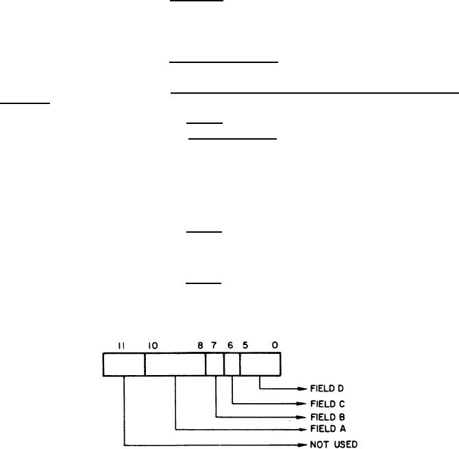
Format of Input Word to Digital Input Multiplexer from TACCO
3.5.1.4.3.5.1
Tray Logic - Refer to Figure 6.
(1) Field A - Identifies the switch group transmitting the data.
BIT
10
9
8
0
0
0
- self encoding keyboard or (30)
Monofunction switch data
0
0
1
- (38) Monofunction switch data
0
1
0
- Matrix Select switch data
1
0
0
- Matrix data
(2) Field B - Identifies test loop operation data; i. e, , if bit 7
is a logical "l", the data contained in the remainder of the input word to the computer is not the result
of a switch depression on the TACCO Tray but is due to test loop operation of the TTL by the computer
program.
(3) Field C - Distinguishes self-encoding keyboard data from the
Monofunction data in the switch group, identified by Field A being binary zero. Keyboard data is iden-
tified by a logical "1" in this position.
Format of Input Word to Digital Input Multiplexer from TACCO Tray Logic
Figure 6.
32
|
|
Privacy Statement - Press Release - Copyright Information. - Contact Us |
