 |
|||
|
Page Title:
Figure 7. Format of Output Word to TACCO Tray Logic from Digital Output Multiplexer |
|
||
| ||||||||||
|
|  MIL-D-81347C(AS)
(4) Field D- Identifies the switch or key depressed in the witch
group or it contains the data resulting from test loop operation.
NOTE
Bits 0-10 of the input word to the DIM will constitute
bits 0-10 of the input word to the computer from the
DIM .
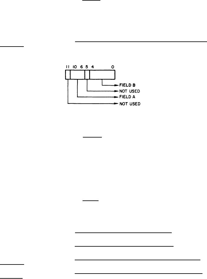
Format of Output Word to TACCO Tray Logic from Digital Output
3.5.1.4.3.5.2
Multiplexer - Refer to Figure 7.
Figure 7.
Format of Output Word to TACCO Tray Logic from Digital Output Multiplexer
(1) Field A- Indicates which of the following operations is to be
performed:
(a) The flip-flop specified by Field B shallbe set or reset.
The flip-flop may control the lighting of a colored background on a Monofunctionor Matrix switch, or
the flip-f lop may control the enabling of a test loop.
(b) Reset a group of flip-flops. The flip-flop may control the
illumination of colored backgrounds on the Matrix A or Matrix B or Matrix C switches or Monofunction
switch group 1 or 2,
(c) Bits 0-3 of Field B constitute a message combination
selection code for Matrix A, or B, or C and shall be stored in the appropriate register.
(2) Field B - Depending upon the Field A code, this field shall
indicate one of the following:
(a) The flip-flop to be set or reset
(b) The Matrix message combination selection code
TACCO Tray Logic to Digital Input Multiplexer - Communications
3.5.1.4.3.5.3
between the TTL and DIM shall be in accordance with 3.5.1.4.1.
Digital Output Multiplexer to TACCO Tray Logic - Communica-
3.5.1.4.3.5.4
tions between the DOM and the TTL shall be in accordance with 3.5.1.4.2.
3.5.1.4,3.5.5
Clock Signal from Maintenance Control Panel Logic to TACCO
Tray Logic - A 10 millisecond clock signal for the TTL shall be generated in the MCPL.
Data Bits 0-4 from Maintenance Control Panel Logic to TACCO
3.5.1.4.3.5.6
Tray Logic - Computer output data bits 0-4 shall be buffered in the MCPL.
33
.
|
|
Privacy Statement - Press Release - Copyright Information. - Contact Us |
