 |
|||
|
Page Title:
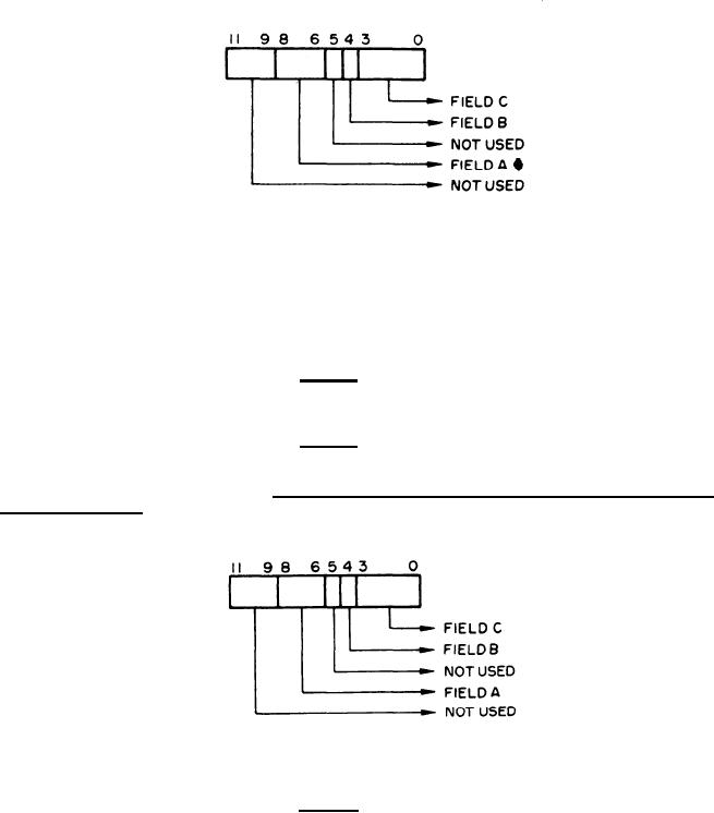
Figure 15. Format of Output Word to CRT Tray Logic from Digital Output Multiplexer |
|
||
| ||||||||||
|
|  MIL-D-81347C(AS)
Format of Output Word to CRT Tray Logic from Digital Output Multiplexer
Figure 15.
(d) Reset all five storage registers.
In addition to one of the operations described above, Field A
shall also enable or disable (depending upon Field B) one of the test loops in the Logic Subunit.
(2) Field B - A logical "l" shall enable the test loop specified
by Field A. A logical "O" shall disable the test loop specified by Field B. This bit is stored in the
same register as the Field C bits.
(3) Field C - The interpretation and storage location of Field C
depends upon Field A.
Format of Output Word to Ordnance Panel Logic from Digital
3.5.1.4.5.5.4
Output Multiplexer - Refer to Figure 16.
For mat of Output Word to Ordnance Panel Logic from Digital Output Multiplexer
Figure 16.
(1) Field A - Specifies which one of the following operations is
to be performed.
(a) Field C is a message selection code for one of the four
PRO's and shall be stored in the storage register allotted to that PRO. There are four Field A codes
required for this purpose.
(b) Field C is the message selection data for the Status
Readout and Alert Signals and shall be stored in the appropriate register.
(c) Reset all five storage registers.
48
|
|
Privacy Statement - Press Release - Copyright Information. - Contact Us |
