 |
|||
|
Page Title:
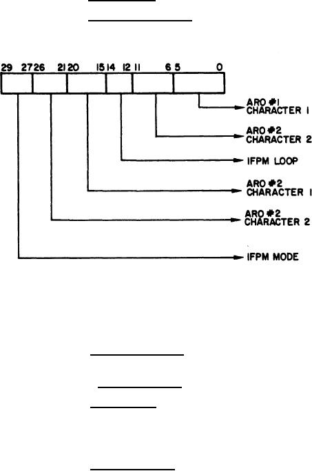
Figure 44. Format of Output Word from Computer to ARO Logic via Maintenance Control Panel |
|
||
| ||||||||||
|
|  MIL-D-81347C(AS)
Word Formats
3.5.1.4.8.4.5
Output Word Formats - The format for the word transferred from
3.5.1.4.8.4.5.1
the computer to the ARO Logic Subunit via the Maintenance Control Panel shall be as shown in Figure 44.
Figure 44. Format of Output Word from Computer to ARO Logic via Maintenance Control Panel
The six-bit character codes for displayed symbols shall be in con-
formance with Figure 49 in which the six-bit character code is presented in octal form.
Input Word Formats - The ARO Logic Subunit shall transmit up to
3.5.1.4.8.4.5.2
30-bit words to the computer.
3.5.1.4.8.5
Operation
Transfer Data - In the On Line mode of operation, data is trans-
3.5.1.4.8.5.1
ferred from the computer to the ARO Logic. The ARO Logic, on sensing the presence of an Output
Acknowledge signal, loads the computer word into the input registers and initiates the display sequence.
In the test modes, an internally generated acknowledge signal is substituted for the computer Output
Acknowledge signal.
Display Character (Refer to Figures 50, 51 and 52) - Upon receipt
3.5.1.4.8.5.2
of an Output Acknowledge, a 40 microsecond settling time delay is initiated. At the end of this delay ,
an unblinking signal is sent to each display unless a Blank Code (36) has been detected. The start of
the unblank time initiates a delay of 16 microseconds. At the end of this time the unblinking signals
are reset to a logical "O", the horizontal position is advanced one step to the right, and the contents of
the input register's Character 2 codes are sat to the ARO Display selection circuits. This again ini-
tiates the 40 microsecond settling time delay. At the end of this delay, an unblinking signal is sent to
each display unless a Blank Code (36) has been received. The start of unblank time initiates two more
delays, one of 12 microseconds, and one of 16. At the end of the 12 microsecond delay, if the charac-
ter is not the twentieth in the row, an Output Data Request is sent to the computer. At the end of the
16 microsecond delay, the unblank is reset, the horizontal position advanced, and the input register is
cleared. If the character was the twentieth in the row, the 12 microsecond delay is changed to 140
microseconds before initiating the Output Data Request. The 16 microsecond delay still resets the un-
blinking signals, but it also clears the horizontal position counter (reset to the left side) and advances
the vertical position one step downward.
85
|
|
Privacy Statement - Press Release - Copyright Information. - Contact Us |
