 |
|||
|
Page Title:
Data Analysis Logic Unit MX-8024A/AYA-8 (Logic Unit 2) |
|
||
| ||||||||||
|
|  MIL-D-81347C(AS)
Data Analysis Logic Unit MX-8024A/AYA-8 (Logic Unit 2)
3.5.2
3.5.2.1
Function: See 3.4.8.
Form Factor: Refer to illustration in EI-515, Avionics Installa-
3.5.2.2
tion Instructions for Data Analysis Programming Group AN/AYA-8B.
3.5.2.3
W e i g h t : see 3.5.1.3.
Contents: See 3.4.3.
3.5.2.4
Magnetic Tape Control Subunit
3.5.2.4.1
Functional Description - The Magnetic Tape Control (MTC) pro-
3.5.2.4.1.1
vides the computer with acessto, and control up to Magnetic Tape Transports (MTT). The
MTC converts the 30-bit computer words into a form acceptable to the MTT, and interprets the in-
structions issued by the computer. The MTC converts the MTT characters into 30-bit words accept-
able to the computer, and notifies the computer of certain specified occurrences (Interrupts) which
affect subsystem operation.
The Digital Magnetic Tape Subsystem (DMTSS) shall be capable
of operating at 75 inches per second under program control.
Figure 56 is a Functional Flow Diagram of the MTC. Figure 57
is a block diagram of the DMTSS.
General Description - The MTC shall be used to disassemble the
3.5.2.4.1.2
computer word, during output operations, into 6-bit characters and to reassemble the 6-bit characters
into computer words, during input operations. The MTC shall also be used to store the "Identifier
word" during a search operation and perform the search operation compare.
3.5.2.4.1.3
Operating Requirements
3.5.2.4.1.3.1
Word Arrangement - The MTC shall handle four types of computer
words:
(1) Data Words
(2) Function Words
(3) Identifier Words
(4) Status Words
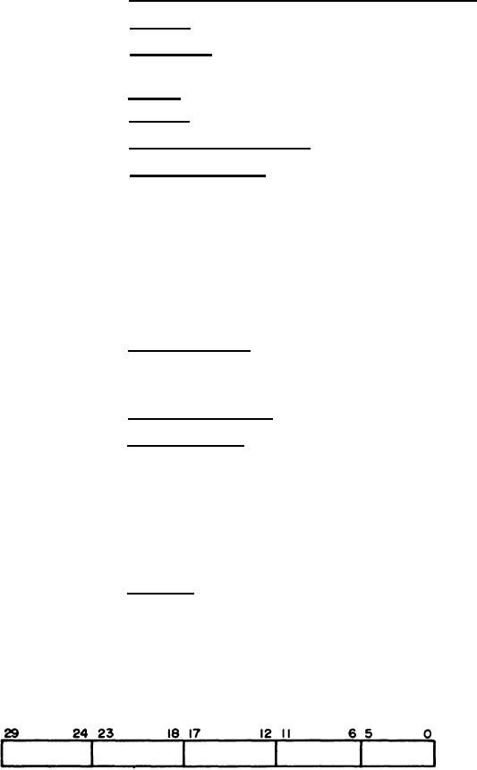
Data Word - The Data word (input or output) is arranged in groups
3.5.2.4.1.3.1.1
of 6-bit characters as shown in Figure 54.
During an output operation the MTC stores the Data word in its
assembly - disassembly register. When the MTC is ready for an output transfer, it disassembles the
Figure 54. Format for Data Word between Computer and Magnetic Tape Control .
97
|
|
Privacy Statement - Press Release - Copyright Information. - Contact Us |