 |
|||
|
Page Title:
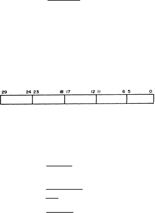
Figure 55. Identifier Word from Computer to Magnetic Tape Control |
|
||
| ||||||||||
|
|  MIL-D-81347C(AS)
30-bit word into 6-bit characters and transfers these MTC characters (one at a time) to the MTT.
During input operations the MTC assembles the 6-bit characters received (one at a time) from the
MTT into a 30-bit computer word.
Function Word - The Function word contains the operating instruc-
3.5.2.4.1.3.1.2
tions. The Function Code (FC) is contained in bits 27 -24. The MTC on receiving a Function word,
decodes the lower 4 bits (FC). The decoded finction Code sets the operating mode for the MTC. The
MTC uses the Function Code to direct the operation of the tape transport. The Function word is always
accompanied by an External Function signal which differentiates the Function word from a Data word.
NOTE
A Function word will be required before any opera-
tion is initiated.
Bits 17 and 18 are used to select any one of the possible MTT's
Transport select for this operation is by bit position rather than binary code. Bits 20 and 21 select
density while bit 19 selects lateral parity format.
Identifier Word - The Identifier word is a full length computer
3 . 5 . 2 . 4 . 1 . 3. 1.3
word which immediately follows a Search-Read Function word; it is arranged in groups of 6-bit
characters as shown in Figure 55.
Figure 55. Identifier Word from Computer to Magnetic Tape Control
The Identifier word may contain any bit configuration except that
bits 24 through 27 may not be zeros simultaneously. It is sent to the MTC accompanied by an External
Function signal. The Identifier word is stored in the MTC assembly-disassembly register and com-
pared with each 30-bit Search word. The comparison is accomplished by the MTC search comparison
circuit.
Status Word - The Status word contains the error information
3.5.2.4.1.3.1.4
generated by the MTC and status conditions of the selected MTT. When the MTC has accumulated all
error and status information, it sends an External Interrupt signal to the computer. A normal input
transfer of the Status word is then initiated.
3.5.2.4.1.3.2
Control Operation
Parity - The MTC will provide both lateral and longitudinal
3.5.2.4.1.3.2.1
parity generation and detection.
Lateral Parity - During a write operation a Lateral Parity bit
3.5.2.4.1.3.2.1.1
shall be added to each six-bit character according to the format specified by the Function word and
the resultant seven bits recorded as one frame. Either odd (total number of "1'`s" in a frame is odd)
or even (total number of "1 `s" in a frame is even) Lateral Parity must be specified by the Function
word. If the MTC detects a frame whose Lateral Parity does not agree with that specified, during a
read type operation or during the post-write check of the record type operation, a Lateral Parity
Error shall be generated. The parity former shall also detect an all zero character and record the
following codes for the specified parity.
98
|
|
Privacy Statement - Press Release - Copyright Information. - Contact Us |
