 |
|||
|
Page Title:
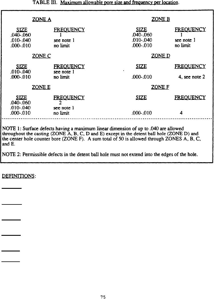
Table 3. Maximum allowable pore size and frequency per location |
|
||
| ||||||||||
|
|  MIL-F-63446B (AR)
ZONE A - The length of the firing pin bore (.158''+.003" in diameter) extending back from the
slider slot a distance of 1.4" + 1/64" (see figure 1).
ZONE B - The length of the firing pin bore extending back from the end of ZONE A to and
including all surfaces of the firing pin cap counterbore (.218"+.003" diameter). (see figure 1).
ZONE C - All other surfaces of the casting excluding the detent ball hole (ZONE D) and the center
hole counterbore (ZONE F).
ZONE D - The surface of the detent ball hole included within the arc of 90, the center of which is
the nominal contact point of the detent ball (see figure 1).
ZONE E - The surface of center hole (.237''+.003" diameter).
ZONE F - The surface of center counterbore (.313"+.004" diameter).
|
|
Privacy Statement - Press Release - Copyright Information. - Contact Us |
