 |
|||
|
|
|||
| ||||||||||
|
|  MIL-F-81150A(OS)
4.4.4.9.2 Decrease the oscillator frequency below 7 KHz until the out-
put voltmeter indicates 30 db below 1 vrms. When this indication is ob-
tained, record the frequency indicated on the electronic counter. This
frequency shall not be lower than 4 KHz.
4.4.4.9.3 Increase the oscillator frequency above 7 KHz until the out-
put voltmeter again indicates 30 db below 1 vrms and record the frequency
indicated on the electronic counter. This frequency shall not be greater
than 13 KHz.
4.4.4.10 To measure the insertion loss as set forth in 3.4.8:
4.4.4.10.1 Adjust the oscillator frequency control until the electronic
counter indicates the center frequency determined in 4.4.4.7.2. Move the
input voltmeter probe to pin 1 of the filter. Then set the oscillator
output for 1 vrms as indicated on the output voltmeter.
4.4.4.10.2 Record the voltage indicated on the input voltmeter. Com-
pute the insertion loss in decibels from the following expression:
Insertion loss (in db) = 20
V
where V is the voltage recorded in 4.4.4.10.2.
The insertion loss shall be less than 1.5 db.
4.4.4.11 To measure the input and output impedance as set forth in
3.4.1:
4.4.4.11.1 Set the oscillator frequency to the center frequency deter-
mined in 4.4.4.7.2. Set the oscillator output to 1 vrms, as indicated
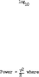
on the output voltmeter. Using the expression:
V = voltage indicated on output voltmeter, and
R = load resistance,
compute the power dissipated in the load resistance.
4.4.4.11.2 Without adjusting the input voltage, change the load resis-
tance to 0.150 megohm (4.4.3.11), 0.180 megohm (4.4.3.12), 0.190 megohm
(4.4.3.13), 0.210 megohm (4.4.3.14), 0.220 megohm (4.4.3.15), and 0.250
megohm (4.4.3.16). For each resistance, compute the power dissipated in
the load resistance, using the expression given in 4.4.4.11.1. Maximum
12
|
|
Privacy Statement - Press Release - Copyright Information. - Contact Us |