 |
|||
|
Page Title:
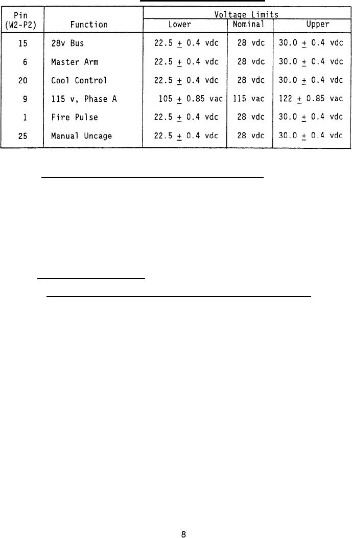
Table IV. Pylon interface test limits. |
|
||
| ||||||||||
|
|  MIL-G-85299(AS)
TABLE IV.
Pylon interface test limits.
3.4.4.2 Test set, launcher/ pylon interface requirements. The test set
shall be connected to test the launcher by installing the igniter contact
block of Cable Assembly W1 in the launcher rails; and connecting one
connector of Cable Assembly W1 to the launcher interface, and the other
connector to J1 of the test set. Connection to the pylon interface shall
require connection of adapter W2 between the pylon connector and W1P2 of
Cable Assembly W1. The igniter contact block shall be a lug support part of
Cable Assembly W1 that mounts on the launcher rail and provides the
electrical connections between the test set and motor igniter circuits in
the aircraft/launcher.
3.4.5 Functional requirements.
3.4.5.1 Ground interface requirements, LAU-7 and py lon test modes.
a.
Ground return
(1) Launcher - W1, P2-21
(2) Pylon - W2, P2-18
(3) Description:
Ground return line for all test set ac and dc inputs
and outputs.
b.
Power interlock ground
(1) Launcher - W1, P2-14
(2) Pylon - W2, P2-26
(3) Description: Provides switch contact closure (not greater than 10
ohms) to power ground in all positions of the test set FUNCTION
SELECT switch except the OFF position. OFF position resistance to
ground shall be not less than 100K ohms.
|
|
Privacy Statement - Press Release - Copyright Information. - Contact Us |
