 |
|||
|
Page Title:
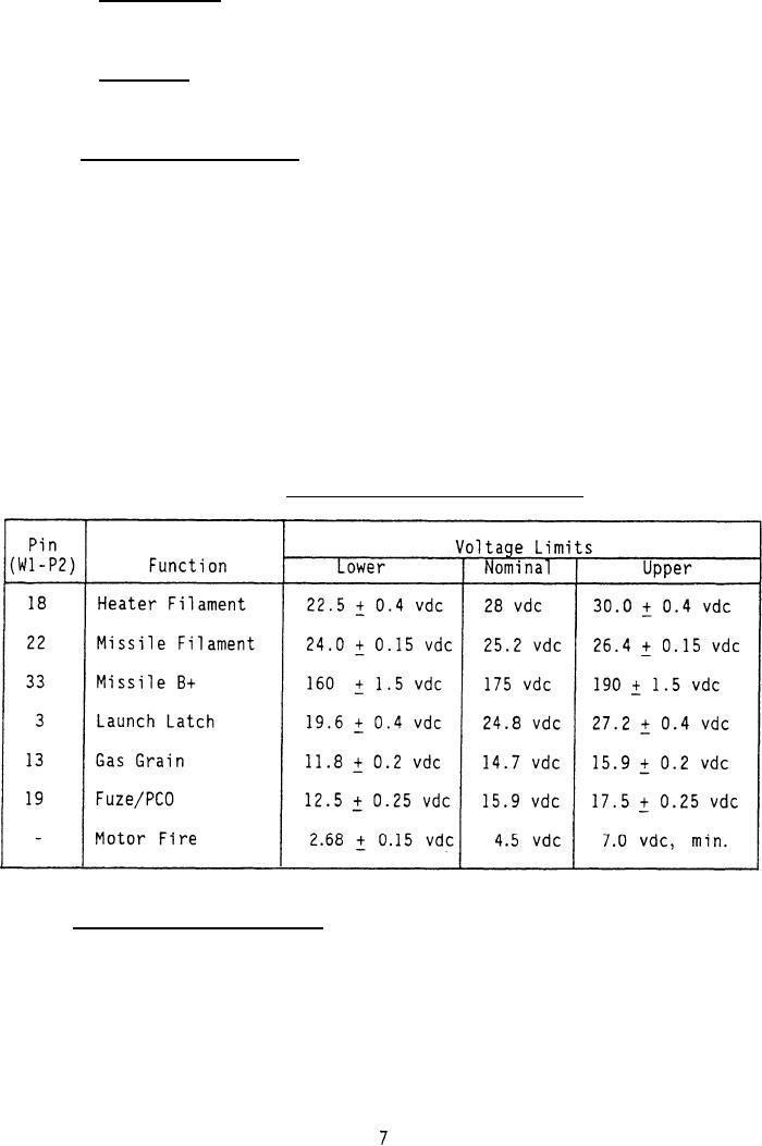
Table III. Launcher interface test limits. |
|
||
| ||||||||||
|
|  MIL-G-85299(AS)
3.4.3.2 Warm-up time. Warm-up time shall be from 1.5 to 25 seconds as
indicated by the SELECTED FUNCTION GO/NO-GO lights in the FUNCTION SELECT TD
position.
3.4.3.3 Lamp test. A lamp test of the SELECTED FUNCTION GO/NO-GO and
STRAY ENERGY GO/NO-GO lamps shall be performed in the FUNCTION SELECT switch
TD position.
3.4.4 Interface requirements. The test set shall be capable of physical and
electrical interface to the launcher LAU-7A or to the aircraft pylon for
performance of tests. Table III lists the tests and the electrical interface
required to perform launcher tests. Table IV specifies interface requirements
for pylon tests. Tables IV and V contain the accept and reject limits for
launcher and pylon interface requirements. The ranges specified for the
upper and lower voltage limits are the transition regions between the
illumination of the GO and NO-GO lamps. When a signal being tested is
between the transition regions, the GO lamp shall illuminate. When a signal
being tested is within a transition region either the GO or the NO-GO lamp
may illuminate. When a signal being tested is beyond the minimum lower
limit or the maximum upper limit, the NO-GO lamp shall illuminate. The test
set shall be connected to the launcher by cable W1 or to the pylon connector
using pylon adapter W2 and cable W1. All requirements and limits shall be
specified at the cable W1, P2 interface for both launcher and pylon functions.
TABLE III.
Launcher interface test limits.
3.4.4.1 Stray energy requirements.
Critical circuits (Fuze/PCO, Gas Grain,
and Motor Fire) shall be continuously monitored for stray electrical energy.
A front panel mounted STRAY ENERGY GO indicator lamp shall be illuminated as
long as no stray energy in excess of safe limits is detected. Measurement
of stray energy shall be inhibited when a functional test is being performed
on the line in question. Stray energy in excess of safe limits shall light
the STRAY ENERGY NO-GO indicator lamp.
(Stray energy criteria is specified
in table V.)
|
|
Privacy Statement - Press Release - Copyright Information. - Contact Us |