 |
|||
|
|
|||
| ||||||||||
|
|  MIL-G-85299(AS)
Frequency BIT.
c.
(1) The audio oscillator frequency shall be checked against the master
crystal oscillator in FUNCTION SELECT positions one through four.
(2) In FUNCTION SELECT position four, the acquisition lambda signal
frequency shall be checked.
(3) The regulator load signal frequency shall be checked with the
PROGRAM switch set to the LAU-7 position and the FUNCTION SELECT
switch in position two.
Phase BIT. The phase relationship between the acquisition lambda
d.
signal and the left-right reference signal shall be tested when the
FUNCTION SELECT switch is in position four.
Stray energy BIT. In FUNCTION SELECT position three, the one
e.
millisecond pulse response of all three stray energy detector hybrid
circuits shall be tested.
Load circuit BIT. In FUNCTION SELECT Positions one through three, the
f.
operation of all pulse load transistors shall be tested whenever they
are operating. The voltage waveforms at the transistor collector shall
be compared with the waveform of the pulse which shall drive the
transistor.
3.4.5.5 Digital voltmeter.
a.
The test set shall have a built-in digital voltmeter capable of
measuring both ac and dc voltages. The meter shall have full scale
ranges of 4.99, 49.9 and 499 volts. The display shall be blanked
except when the PRESS TO TEST DVM/RESET push-button is depressed.
For ac voltage measurement, the meter shall be rms calibrated and
b.
average responding. The accuracy of the reading shall be three
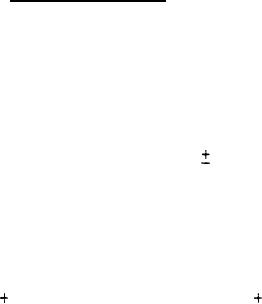
percent of full scale
one digit for frequencies of 100 Hertz to
six kilohertz.
c.
For dc voltage measurements, the reading shall be an instantaneous
value stored by a sample and hold circuit. Updating of measurement
shall occur at a one Hertz rate. Updating shall be between the 14th
and 18th milliseconds of the 20 milliseconds, one Hertz, repetitive
load pulses, where applicable. The accuracy of the readings shall be
two percent of full scale
one digit of the instantaneous
interface voltage.
d.
The voltmeter input shall be connected to the various input and output
lines by the use of the LINE SELECT switch. The relationships of the
LINE SELECT switch positions and the input and output pins shall be as
specified in table VII. For LINE SELECT positions four through eight,
and 11 through 24, the input impedance of the selected interface pin
shall be modified by an additional 100K ohms resistance in parallel to
ground.
19
|
|
Privacy Statement - Press Release - Copyright Information. - Contact Us |