 |
|||
|
|
|||
| ||||||||||
|
|  MIL-H-48408A(MU)
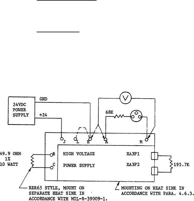
3.3.3.3 Inhibit voltage
test.- When 24 6 VDC is applied to Pin "J"
of connector P1, Pin "L" and
Pin "E" of P1 are grounded and a total resis-
tance of 195.7K 2% OHMS is
connected across XA3P1 and XA3P2, the voltage
measured between Pin "A" and
Pin "E" of Connector "J1" shall be 135 10
VDC,
3.3.3.4 Flash mode test. - When Pin "E" of Connector "JI" is connect-
ed to ground and 24 6 VDC is applied to Pin "J" for a period of 0.5
second; minimum and Pin "L" is simultaneously grounded for a period of
100 milliseconds from the gated output of Timing Module 11737703. The
voltage waveform appearing at Pin "L" shall be as shown in Figure 2 and
the voltage waveform appearing at Pin "A" shall be as shown in Figure 3.
A total resistance of 195.7K 2% OHMS shall be connected across XA3P1 and
XA3P2 during this test.
FIGURE I
4
|
|
Privacy Statement - Press Release - Copyright Information. - Contact Us |