 |
|||
|
|
|||
| ||||||||||
|
|  MIL-L-82452A(OS)
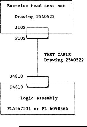
FIGURE 3.
Logic Assembly test setup.
d.
Position rpm level control to 32 and rpm freq switch to 1900.
Digital dc voltmeter shall indicate -0.35 to -0.55 Vdc.
Vary rpm level control from 28 to 36. Digital dc voltmeter
e.
indication shall not vary more than 10 mv.
f.
Position rpm level control to 32 and rpm freq switch to 1800.
Digital dc voltmeter shall indicate -0.7 to -1.0 Vdc.
Vary rpm level control from 28 to 36. Digital dc voltmeter
g.
indication shall not vary more than 10 mv.
h.
Return rpm switch to center position.
4.7.3.5 Turnaway circuit.
Verify that normal steering indicator is illuminated.
a.
b.
Position range switch to R<B. Normal steering indicator shall
extinguish and reverse steering indicator shall illuminate.
c.
Position turnaway ko switch to "down". Reverse steering indica-
tor shall extinguish and normal steering indicator shall
illuminate.
d.
Position turnaway ko switch to "up" and range switch to R>B.
19
|
|
Privacy Statement - Press Release - Copyright Information. - Contact Us |
