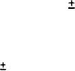
 |
|||
|
|
|||
| ||||||||||
|
|  MIL-L-82452A(OS)
4.7.3.6 Squib logic circuit.
4.7.3.6.1 Connect digital dc voltmeter between "aid ind" jack and
"ground" jack on test set panel.
4.7.3.6.2 Hold inertia switch down momentarily.
DCO squib, termination
squib, and recovery indicators shall illuminate.
4.7.3.7 Power failure circuit.
Position logic power switch to "off". Power failure indicator
a.
shall illuminate for 4 to 6 seconds. Digital dc voltmeter
shall indicate +39.0 to +41.0 Vdc.
b.
Digital dc
Hold dco-ald reset switch momentarily to ald reset,
voltmeter shall indicate -0.01 to +0.01 Vdc.
TYPE II ONLY. Position 200 ft. switch to "on". DCO squib indicator
shall illuminate. Position logic power switch to "on". DCO squib
indicator shall extinguish.
Position logic power switch to "off".
DCO squib indicator shall illuminate. Position 200 ft. switch to
"off". DCO squib indicator shall extinguish.
Position logic power switch to "on" and momentarily hold dco-ald
c.
reset switch to dco position. Dco squib and termination squib
indicators shall illuminate when switch is in dco position,
Position logic power switch to "off".
d.
Position logic power switch to "on". After 8 to 9 seconds has
elapsed, position logic power switch to "off". Power failure
indicator shall not illuminate.
e.
Position logic power switch to "on". After 11 to 12 seconds
have elapsed, position logic power switch to "off". Power
failure indicator shall illuminate.
4.7.3.8
Minus 10 volt regulator circuit.
a.
Connect digital dc voltmeter to meter monitor jack and position
dc volts switch to -10.
b.
Digital dc voltmeter shall
Position logic power switch to "on".
indicate -9.5 to -10.5 Vdc.
Position dc volts switch to -40 and adjust -40V power supply on
c.
test set for -38
0.5 Vdc indication on digital dc voltmeter.
Position dc volts switch to -10 and record voltage indicted on
digital dc voltmeter.
Position dc volts switch to -40 and adjust -40V power supply for
d.
Position dc
-42.0
0,5 Vdc indication on digital dc voltmeter,
20
|
|
Privacy Statement - Press Release - Copyright Information. - Contact Us |