 |
|||
|
Page Title:
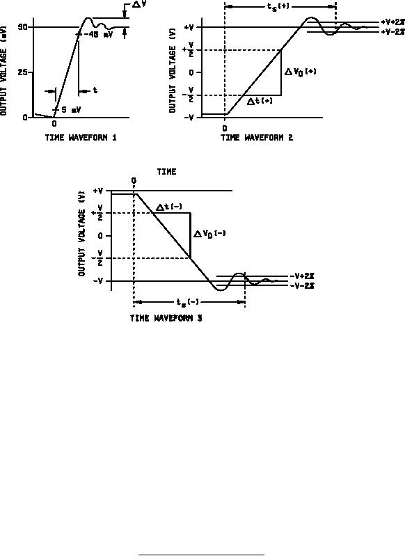
Figure 5. Transient response test circuit notes |
|
||
| ||||||||||
|
|  MIL-M-38510/101H
NOTES:
1.
Idle half of dual amplifier shall be connected during test of other half.
All resistor tolerances are 1 percent, capacitor tolerances are 10 percent and VCC = 20 V.
2.
3.
This compensation capacitor is used for device types 03, 04, 05, and 06.
For device types 01, 02, 03, 05, and 08, RL = 2 kΩ; for device types 04 and 06, RL = 10 kΩ.
4.
5.
Settling time is the interval from the beginning of the output response to the point where the output remains
within the error band, in this case 2 percent.
CF = 10 pF 10 percent includes stray capacitance.
6.
R1 may be added to the circuit. When R1 is added, its value shall be 10 kΩ. When using R1, the unity gain
7.
will increase to 2. To accommodate this change in gain, the pulse generator input shall be halved.
8.
C1 may be added to the circuit. When added, it shall be within the range of 0 pF to 2 pF.
CL capacitance specified includes stray, jig, and probe capacitance.
9.
FIGURE 5. Transient response test circuit - Continued.
30
|
|
Privacy Statement - Press Release - Copyright Information. - Contact Us |
