 |
|||
|
Page Title:
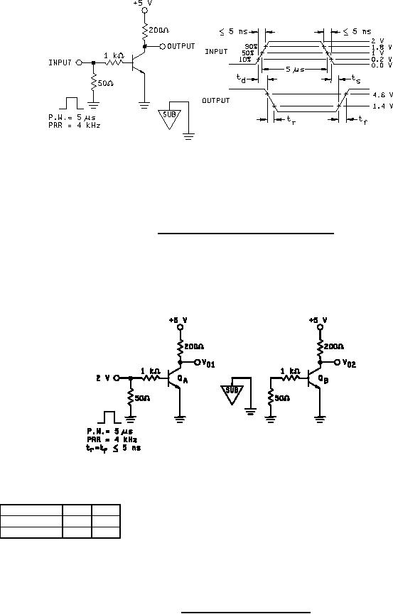
Figure 2. Switching time test circuit and waveforms. |
|
||
| ||||||||||
|
|  MIL-M-38510/108A
FIGURE 2. Switching time test circuit and waveforms.
Notes:
1.
Device type
QA
QB
01
Q1
Q2
02
Q3
Q4
2. Measure V01, V02, (volts peak)
3. Isolation = 20 log (V01/V02)
FIGURE 3. Channel separation test circuit.
11
|
|
Privacy Statement - Press Release - Copyright Information. - Contact Us |
