 |
|||
|
Page Title:
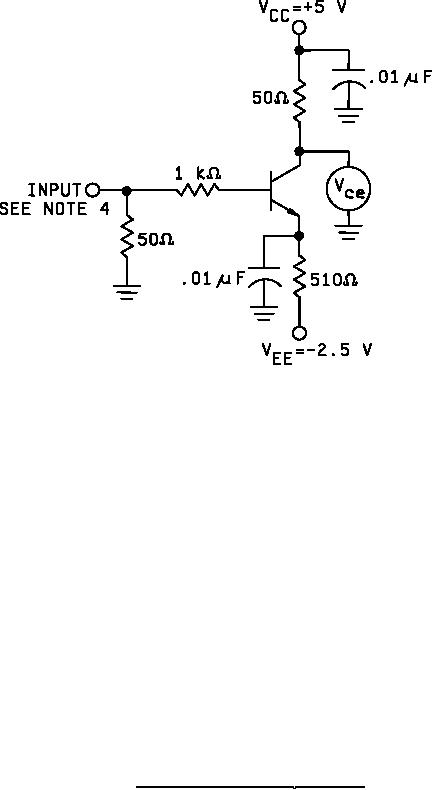
Figure 4. Gain-bandwidth product (ft) test circuit. |
|
||
| ||||||||||
|
|  MIL-M-38510/108A
Notes:
1. The input shall be a 100 MHz signal containing only the fundamental frequency (THD ≤ 0.5%).
2. Connect the substrate to 2.5 V.
3. With the device removed from the circuit, a shorting link is placed between the base and collector
and the input signal adjusted for 1.0 mV rms on the high impedance voltmeter Vce. The shorting
link is then removed. The device is placed in the circuit and the reading on the voltmeter Vce equal
to the magnitude of hfe.
4. ft = 100 MHz x hfe
FIGURE 4. Gain-bandwidth product (ft) test circuit.
12
|
|
Privacy Statement - Press Release - Copyright Information. - Contact Us |
