 |
|||
|
Page Title:
Table 1. Electrical performance characteristics-cont. |
|
||
| ||||||||||
|
|  MIL-M-38510/117C
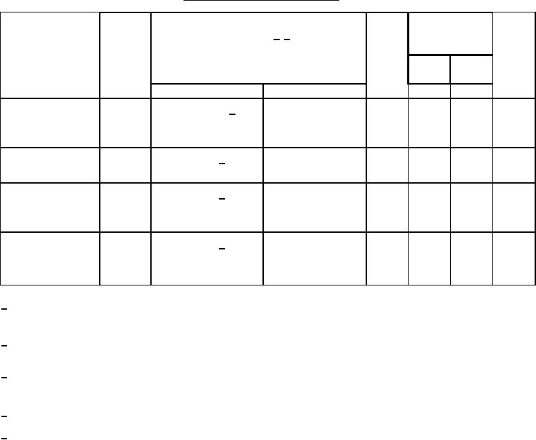
TABLE I. Electrical performance characteristics Continued.
Conditions 1/ 2/
Device
Limits
Unit
Test
Symbol
type
-55C ≤ TA ≤ +125C
see figure 10 and 3.5
Min
Max
unless otherwise specified
Input voltage
Load current
Ripple rejection
06
65
dB
ĆVIN /
IL = -500 mA,
VIN = 6.25 V,
4/
ĆVOUT
TA = 25C,
ei = 1 Vrms,
at f = 2400 Hz
see figure 11
Vrms
Output noise voltage
06
120
VIN = 6.25 V, 4/
IL = -100 mA,
VNO
see figure 12
TA = 25C
Line transient
06
12
mV/V
ĆVOUT /
VIN = 6.25 V, 5/
IL = -10 mA,
response
TA = 25C
ĆVIN
ĆVIN = 3.0 V,
see figure 13
06
0.30
mV/mA
Load transient
ĆVOUT /
VIN = 6.25 V, 5/
IL = -100 mA,
response
see figure 14
ĆIL
ĆIL = -400 mA
TA = 25C
All tests performed at TA = 125C may at the manufacturer's option, be performed at TA = 150C.
1/
Specifications for TA = 125C shall then apply at TA = 150C.
2/
Static tests with load currents greater than 5 mA are performed under pulsed conditions defined on figures 9 or
10 as applicable.
3/
Output voltage recovery test shall be performed, with the designated load conditions, immediately after removal
of each IOS test forced output voltage condition.
4/
The meter for ei and eo shall have a minimum bandwidth from 10 Hz to 10 kHz and shall measure true rms voltages.
5/
The oscilloscope shall have a bandwidth between 5 and 15 MHz.
17
|
|
Privacy Statement - Press Release - Copyright Information. - Contact Us |