 |
|||
|
Page Title:
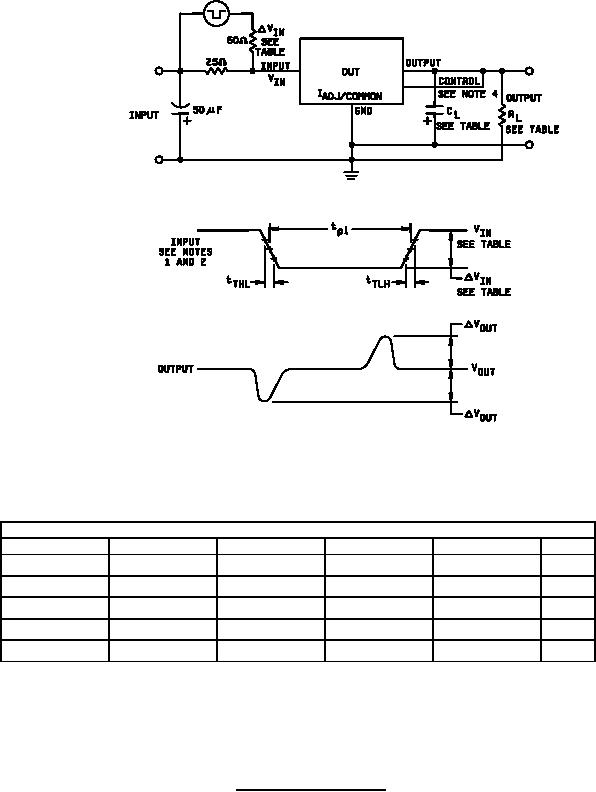
Figure 12. Line transient test circuit. |
|
||
| ||||||||||
|
|  MIL-M-38510/118B
Device table
Device type
01
02
03
04
Notes
-10 V
-10 V
-6.25 V
-6.25 V
1
VIN
-3.0 V
-3.0 V
-1.0 V
-1.0 V
1
ĆVIN
1.25 kΩ
1.25 kΩ
25 Ω
12 Ω
RL
5.0 s
5.0 s
5.0 s
5.0 s
1
tTHL = tTLH
2.0 F
2.0 F
1.0 F
1.0 F
Ci, CL
NOTES:
1. Measured at device input.
2. Pulse width tp1 = 25 s; duty cycle = 3% (maximum).
3. Oscilloscope bandwidth = 5 MHz to 15 MHz.
4. The control pin connection is required for device types 01 and 02 only..
FIGURE 12. Line transient test circuit.
29
|
|
Privacy Statement - Press Release - Copyright Information. - Contact Us |
