 |
|||
|
|
|||
| ||||||||||
|
|  MIL-M-38510/118B
Device table
Device type
01
02
03
04
10 V
10 V
6.25 V
6.25 V
VIN
100 Ω
50 Ω
25 Ω
12.5 Ω
RL
2.0 F
2.0 F
1.0 F
1.0 F
Ci, CL
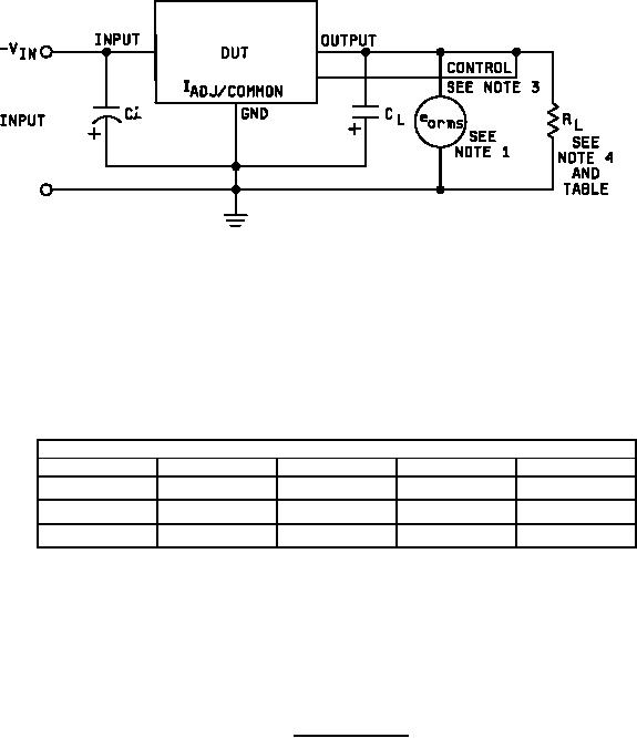
NOTES:
1. The meter for measuring eorms and shall have a minimum bandwidth from 10 Hz to 10 kHz and
shall measure true rms voltages.
2. NO = eorms
3. The control pin connection is required for device types 01 and 02 only.
4. RL shall be type RER 70 or equivalent.
FIGURE 11. Noise test circuit.
28
|
|
Privacy Statement - Press Release - Copyright Information. - Contact Us |
