 |
|||
|
Page Title:
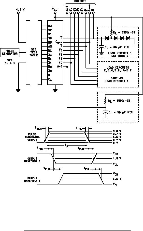
Figure 4. Waveforms for propagation delay time and test circuit for device type 01. |
|
||
| ||||||||||
|
|  MIL-M-38510/11D
NOTES:
The pulse generator has the following characteristics: PRR = 1 MHz 10%, ZOUT ≈ 50 ohms. Pulse width
1.
= 200 ns 10%, tTLH = tTHL ≤ 10 ns.
2.
Load circuits on a given output are only required where the specific test given in table III indicates "OUT" on
that output. Load circuits may otherwise be omitted.
3.
CL includes probe and jig capacitance.
4.
All diodes are 1N3064, or equivalent.
FIGURE 4. Waveforms for propagation delay time and test circuit for device type 01.
17
|
|
Privacy Statement - Press Release - Copyright Information. - Contact Us |
