 |
|||
|
Page Title:
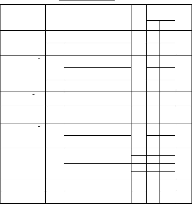
Table 1. Electrical performance characteristics-cont. |
|
||
| ||||||||||
|
|  MIL-M-38510/125B
TABLE I. Electrical performance characteristics Continued.
Conditions
Device
Limits
Unit
Test
Symbol
-55C ≤ TA ≤ +125C
type
VCC = 15 V,
see figure 3 and 3.5
Min
Max
unless otherwise specified
Power supply rejection
+PSRR
01,02
80
dB
+VCC = +12 V to +18 V,
ratio
-VCC = -18 V, VIN = 0 V
-PSRR
80
+VCC = +18 V, VIN = 0 V
-VCC = -12 V to -18 V
Feedthrough rejection 3/
FRR
01,02
86
dB
VIN = 11.5 V, hold mode, see figure 4,
ratio
TA = +25C
80
VIN = 11.5 V, hold mode, see figure 4,
-55C ≤ TA ≤ +125C
86
VIN = 20 VPP at 1 kHz, TA = +25C
FRRac
hold mode, see figure 5
Series charge
4/
01,02
75
400
Ω
RSC
VIN = 0 V to 0.4 V;
resistance
measure current change to ground at
HOLD CAPACITOR terminal pin
Output impedance
01,02
2
Ω
ZO
VHOLD CAP. = VHC = 0 V,
hold mode, see figure 6,
IO = 1 mA
01,02
-2
2
mV
"Hold" step voltage
5/
VLOGIC = 4 V, tr ≤ 50 ns, see figure 7,
VHS
VOUT = 11.5 V, TA = +25C
-5
5
VLOGIC = 4 V, tr ≤ 50 ns, see figure 7,
VOUT = 11.5 V, -55C ≤ TA ≤ +125C
Supply current
01
1
6.5
mA
TA = -55C
ICC
02
1
7.0
01
1
5.5
+25C ≤ TA ≤ +125C
02
1
6.0
Logic input current (high)
01,02
0
10
A
IIH
VLOGIC = 5.5 V, +VCC = 8.5 V,
-VCC = -21.5 V
Logic input current (low)
01,02
-1
1
A
IIL
VLOGIC = 0 V, +VCC = 21.5 V,
-VCC = -8.5 V
See footnotes at end of table.
5
|
|
Privacy Statement - Press Release - Copyright Information. - Contact Us |
