 |
|||
|
Page Title:
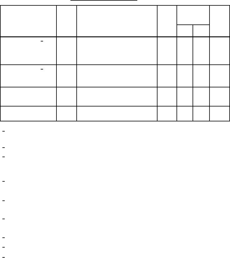
Table 1. Electrical performance characteristics-cont. |
|
||
| ||||||||||
|
|  MIL-M-38510/125B
TABLE I. Electrical performance characteristics Continued.
Conditions
Device
Limits
Unit
Test
Symbol
-55C ≤ TA ≤ +125C
type
VCC = 15 V,
see figure 7 and 3.5
Min
Max
unless otherwise specified
01,02
2.5
Transient response 9/
s
VIN = 100 mV step, TA = +25C,
TR(ts)
(settling time)
CH = 1000 pF, RL = 10 kΩ,
CL = 100 pF, see figure 16,
to 10% of final value,
01,02
40
%
Transient response 9/
VIN = 100 mV step, TA = +25C,
TR(os)
(overshoot)
CH = 1000 pF, RL = 10 kΩ,
CL = 100 pF, see figure 16
Noise
en(H)
Hold mode, sample mode
01,02
10
Vrms
en(S)
10 Hz to 10 kHz,
see figure 17, TA = +25C
Settling time
01,02
1.5
s
VIN = 0 V, VO ≤ 1 mV,
tS
hold mode, see figure 18, TA = +25C
This parameter is specified at VCM = 0 V, -11.5 V, and +11.5 V with VCC = 15 V, and at VCM = -2 V and +2 V with
1/
VCC = 5 V.
2/
Input impedance is calculated from the VIO and IIB common mode voltage end-point range data.
3/
Feedthrough rejection ratio is very sensitive to stray capacitance between the signal INPUT (pin 3 ) and HOLD
CAPACITOR (pin 6). For instance 0.5 pF of external coupling with a .01 F hold capacitor would equal the
specification limit of the device.
4
(For example: FRR = 20 log ((0.01 F) / 0.5 pF) = 20 log (2 x 10 ) = 86 dB).
4/
Series charge resistance along with input signal slew rate and an external hold capacitor determine the
dynamic sampling error of the device in its application (for example; DSE = K x RSC x SR where K is a
proportionality constant).
5/
The external hold capacitor should be either Teflon or polystyrene so that dielectric absorption is minimized.
This will insure that excessive "sag back" after capacitor "sample" mode charging does not occur. "Hold" step
is sensitive to stray capacitance coupling between input logic signals and the "hold" capacitor.
6/
Hold mode leakage current is actually JFET junction leakage current which doubles (approximately) for each
10C increase in junction temperature. Measurement at 55C is not necessary since expected values are too
small for typical test systems.
Acquisition time at 125C typically increases from 20 % to 100 % above the 25C value.
7/
Aperture time at 125C typically increases 110 % above the 25C value.
8/
9/
Transient response shall be measured at the common mode voltage limits (for example, VCM = -11.5 V and
+11.5 V). Any high frequency ringing shall be over within 1 microsecond. After its peak the major loop
response shall be without further oscillations.
7
|
|
Privacy Statement - Press Release - Copyright Information. - Contact Us |
