 |
|||
|
Page Title:
Table 1. Electrical performance characteristics-cont. |
|
||
| ||||||||||
|
| 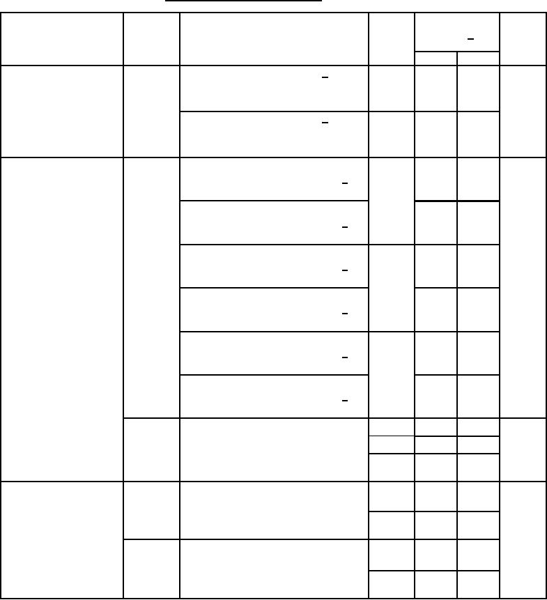 MIL-M-38510/140A
TABLE I. Electrical performance characteristics Continued.
Conditions
-55C ≤ TA ≤ +125C
Device
Limits 1/
Unit
Test
Symbol
type
unless otherwise specified
see 3.6 and figures 4 and 8
Min
Max
01,03,
-1
1
LSB
Bipolar zero drift
Output code = φφφφ φφφφ φφφφ 6/
ĆBZ / ĆT
05
Bipolar, VFSR = 20 V,
TA = 25C, see figures 6 and 8
02,04,
-2
2
Output code = φφφφ φφφφ φφφφ
6/
06
Bipolar, VFSR = 20 V,
TA = 25C, see figure 6 and 8
01
-0.125
0.125
%FSR
Gain error
Output transition = 0000 0000 000φ
AE
and 1111 1111 111φ 6/
Initial
-0.225
0.225
Output transition = 0000 0000 000φ
and 1111 1111 111φ 6/
End point
02
-0.25
0.25
Output transition = 0000 0000 000φ
and 1111 1111 111φ 6/
Initial
-0.35
0.35
Output transition = 0000 0000 000φ
and 1111 1111 111φ 6/
End point
03,04,
-0.3
0.3
Output transition = 0000 0000 000φ
05,06
and 1111 1111 111φ 6/
Initial
-0.4
0.4
Output transition = 0000 0000 000φ
and 1111 1111 111φ 6/
End point
Bipolar, VFSR = 20 V,
01
-0.125
0.125
%FSR
BPAE
02
-0.25
0.25
TA = 25C, see figures 6 and 8
03,04,
-0.3
0.3
05,06
Gain error drift
01,03,
-12.5
12.5
ĆAE / ĆT
Output transition = 0000 0000 000φ
ppm/C
05
and 1111 1111 111φ
02,04,
-25
25
06
01,03,
-12.5
12.5
Bipolar, VFSR = 20 V,
ĆBPAE /
05
ĆT
TA = 25C, see figures 6 and 8
02,04,
-25
25
06
See footnotes at end of table.
9
|
|
Privacy Statement - Press Release - Copyright Information. - Contact Us |
