 |
|||
|
Page Title:
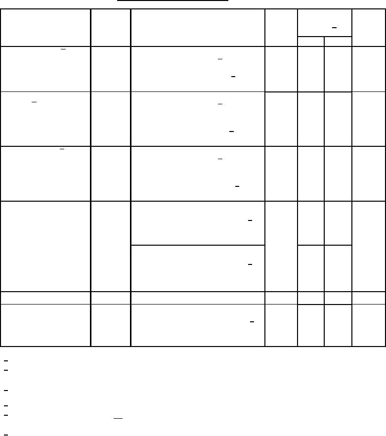
Table 1. Electrical performance characteristics-cont. |
|
||
| ||||||||||
|
|  MIL-M-38510/140A
TABLE I. Electrical performance characteristics Continued.
Conditions
-55C ≤ TA ≤ +125C
Device
Limits 1/
Unit
Test
Symbol
type
unless otherwise specified
see 3.6 and figures 4 and 8
Min
Max
All
600
ns
Low to high transition,
tDS
STS delay from R/ C
referenced to high to low R/ C transition,
output code = 0000 0000 0000 2/
TA = +25C, figures 7 and 8
All
250
ns
Data access time
Output data valid,
tDDR
from R/ C
referenced to low to high R/ C transition,
output code = 0000 0000 0000 and
1111 1111 1111 2/
TA = +25C, figures 7 and 8
All
25
ns
Output data valid,
tHDR
Data valid after R/ C low
referenced to high to low R/ C transition,
output code = 0000 0000 0000 and
1111 1111 1111 2/
TA = +25C, figures 7 and 8
Output short circuit current
All
-40
mA
IOSC
VLOG = 5.5 V,
output code = 1111 1111 1111 and
2/
STS output = logic "1", TA = 25C,
measured separately to ground
75
VLOG = 5.5 V,
output code = 0000 0000 0000 and
2/
STS output = logic "0", TA = 25C,
measured separately to VLOG
Input resistance
Ri
All
3
7
kΩ
VIN(analog) = 1/2 V, TA = 25C
All
-0.5
0.5
LSB
Transition uncertainty
NT
Output transition = φφφφ φφφφ φφφφ
and 1111 1111 1111
6/
Range = 16% to 84%, TA = 25C
(figures 6 and 8)
1/
See paragraph 6.5 for symbols and definitions.
2/
An output code of 0000 0000 0000 is guaranteed by an input voltage VIN = -7.0 mV and an output code
of 1111 1111 1111 is guaranteed by an input voltage VIN = 10.08 V.
3/
PD = (VCC *ICC +VEE *IEE +VLOGIC *ILOGIC). Power dissipation shall be calculated using the two output code
conditions 0000 0000 0000 and 1111 1111 1111.
4/
The reference voltage external load current shall be constant dc and shall not exceed 1.5 mA.
5/
Changing A0 during the ready cycle, may result in damage to the device output buffers. Therefore, it is
recommended that CE is low or CS is high before A0 is changed.
φ represent the transition point between two adjacent code words (for example: 0000 0000 000φ)
6/
represents the transition between code words 0000 0000 0000 and 0000 0000 0001, φφφφ φφφφ φφφφ
represents the transition between code words 0111 1111 1111 and 1000 0000 0000 and
1111 1111 111φ represents the transition between code words 1111 1111 1110 and 1111 1111 1111.
11
|
|
Privacy Statement - Press Release - Copyright Information. - Contact Us |
