 |
|||
|
Page Title:
Table 1. Electrical performance characteristics-cont. |
|
||
| ||||||||||
|
|  MIL-M-38510/141B
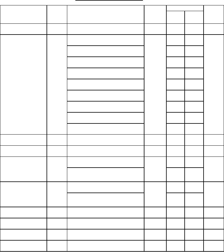
TABLE I. Electrical performance characteristics Continued.
Conditions
Device
Limits
Test
type
Min
Max
Units
-55C ≤ TA ≤ +125C
Symbol
unless otherwise specified
A
Output leakage current
05, 10
10.0
ICEX
VCE = 50 V
Collector emitter
05, 10
1.8
V
IC = 350 mA, IB = 850 A, TA = -55C
VCE(sat)
saturation voltage
1.5
IC = 200 mA, IB = 550 A, TA = -55C
1.3
IC = 100 mA, IB = 350 A, TA = -55C
1.6
IC = 350 mA, IB = 500 A, TA = +25C
1.3
IC = 200 mA, IB = 350 A, TA = +25C
1.1
IC = 100 mA, IB = 250 A, TA = +25C
1.8
IC = 350 mA, IB = 500 A, TA = +125C
1.5
IC = 200 mA, IB = 350 A, TA = +125C
1.3
IC = 100 mA, IB = 250 A, TA = +125C
A
Input current
05, 10
1180
2400
IIN(on)
VIN = 3 V
A
Input current
05, 10
500
IB ≤ 25 A
IIN(off)
Input voltage
05, 10
3.0
V
VCE ≤ 2 V, IC = 350 mA, TA = -55C
VIN(on)
2.4
VCE ≤ 2 V, IC = 350 mA,
+25C ≤ TA ≤ +125C
DC forward current
05, 10
500
VCE = 2 V, IC = 350 mA, TA = -55C
hFE
transfer ratio
1000
VCE = 2 V, IC = 350 mA,
+25C ≤ TA ≤ +125C
A
Clamp diode leakage
05, 10
10.0
IR
VR = 50 V
current
Clamp diode forward
05, 10
2.0
V
VF
IF = 350 mA
voltage
Turn on delay
05, 10
750
ns
TA = +25C, see figure 4
tPLH
Turn off delay
02, 10
300
ns
TA = +25C, see figure 4
tPHL
10
|
|
Privacy Statement - Press Release - Copyright Information. - Contact Us |
