 |
|||
|
Page Title:
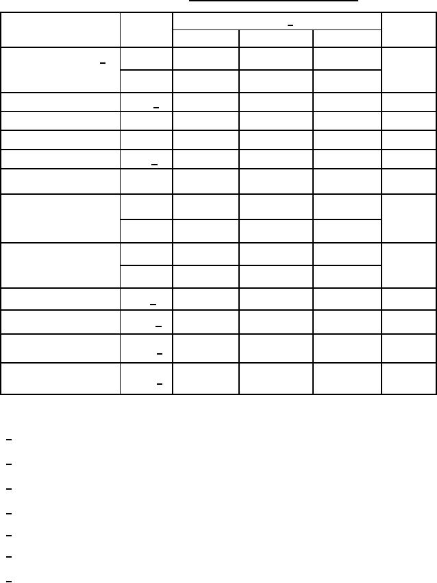
Table 4A. Programming characteristics for circuit A. |
|
||
| ||||||||||
|
|  MIL-M-38510/207E
TABLE IVA. Programming characteristics for circuit A.
Limits 1/
Parameter
Symbol
Unit
Min
Recommended
Max
VIH
Address input voltage 2/
2.4
5.0
5.0
V
0.0
0.4
0.5
"
VIL
Programming
10.75
11.0
11.25
V
VPH 3/
0.0
0.0
1.5
V
Voltage to VCC low
VPL
Program verify
---
5.5
---
V
VPHV
Verify voltage
4.5
5.0
5.5
V
VR 4/
Programming input low
μA
---
-300
-600
IILP
current at VPH
Programmed voltage
μs
1
5
10
tTLH
(VCC) transition time
1
5
10
"
tTHL
μs
Programming delay
10
10
20
tD1
1
5
5
"
tD2
μs
Programming pulse width
90
100
110
tP 5/
Programming duty cycle
PDC 6/
---
30
60
%
Output voltage
10.5
10.5
11.0
V
VOPE 7/
Enable
Output voltage
0.0
5.0
5.5
V
VOPD 7/
Disable
During the programming the chip must be disabled for proper operation.
1/ TC = +25C.
2/ No inputs should be left open for VIH.
3/ VPH source must be capable of supplying one ampere.
4/ It is recommended that post programming dual verification be made at VR minimum and VR maximum.
5/ Note step j in programming procedure.
6/ Programming duty cycle applies to DIPs only.
7/ VOPE source must be capable of supplying 10 mA minimum.
25
|
|
Privacy Statement - Press Release - Copyright Information. - Contact Us |
