 |
|||
|
Page Title:
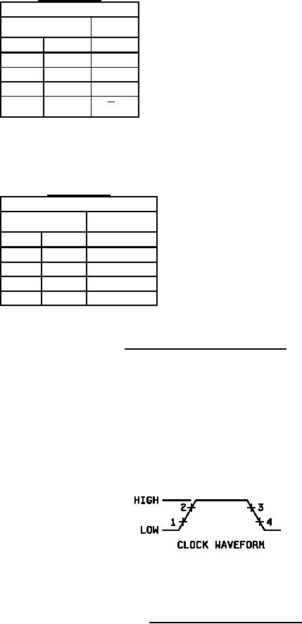
Figure 2. Truth tables and device descriptions. |
|
||
| ||||||||||
|
|  MIL-M-38510/21F
Positive logic:
Low input to preset sets Q to high level
Device type 01
Truth table
Low input to clear sets Q to low level
Preset and clear are independent of clock
tn
tn+1
J
K
Q
NOTES:
L
L
Qn
1. J = J1 J2 J3
L
H
L
2. K = K1 K2 K3
H
L
H
3. tn = Bit time before clock pulse.
4. tn+1 = Bit time after clock pulse.
H
H
Qn
Positive logic:
Low input to preset sets Q to high level
Device type 02
Truth table
Low input to clear sets Q to low level
Preset and clear are independent of clock
tn
tn+1
R
S
Q
NOTES:
L
L
Qn
1. R = R1 R2 R3
L
H
H
2. S = S1 S2 S3
H
L
L
3. tn = Bit time before clock pulse.
H
H
Indeterminate
4. tn+1 = Bit time after clock pulse.
Description for device types 01 and 02
These flip-flops are based on the master slave principle and each has AND gate inputs for entry into
the master section which are controlled by the clock pulse. The clock pulse also regulates the state of
the coupling transistors which connect the master and slave sections. The sequence of operation as
controlled by the clock pulse is as follows:
1. Isolate slave from master.
2. Enter information from AND gate inputs to master.
3. Disable AND gate inputs.
4. Transfer information from master to slave.
Figure 2. Truth tables and device descriptions.
10
|
|
Privacy Statement - Press Release - Copyright Information. - Contact Us |