 |
|||
|
Page Title:
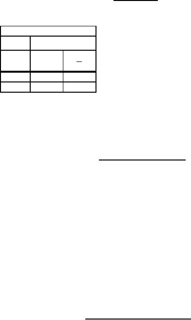
Figure 2. Truth tables and device descriptions device type 05 |
|
||
| ||||||||||
|
|  MIL-M-38510/21F
Device type 05
Positive logic:
Low input to preset sets Q to high level
Truth table each flip-flop
Low input to clear sets Q to low level
Preset and clear are independent of clock
tn
tn+1
Input
Output
Output
D
Q
NOTES:
Q
L
L
Qn
1. tn = Bit time before clock pulse.
L
H
L
2. tn+1 = Bit time after clock pulse.
Description for device type 05
Input information is transferred to the output on the positive edge of the clock pulse. Clock triggering
occurs at a voltage level of the clock pulse and is not directly related to the transition time of the
positive going pulse. After the clock input threshold voltage has been passed, the data input (D) is
locked out.
Figure 2. Truth tables and device descriptions - Continued.
12
|
|
Privacy Statement - Press Release - Copyright Information. - Contact Us |