 |
|||
|
Page Title:
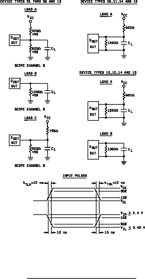
Figure 5. Switching time load circuits, test conditions and waveforms. |
|
||
| ||||||||||
|
|  MIL-M-38510/231C
NOTES:
1. Use load circuit A in transitions between logic level and from high Z state to logic low state.
2. Use load circuit B in transitions from high Z state to logic high state.
3. Use load circuit C in transitions rom a logic level to the high Z state.
4. CL = 30 pF 5% including wiring and probe capacitance.
FIGURE 5. Switching time load circuits, test conditions and waveforms.
15
|
|
Privacy Statement - Press Release - Copyright Information. - Contact Us |
