 |
|||
|
Page Title:
Table 1. Electrical performance characteristics-cont. |
|
||
| ||||||||||
|
|  MIL-M-38510/245B
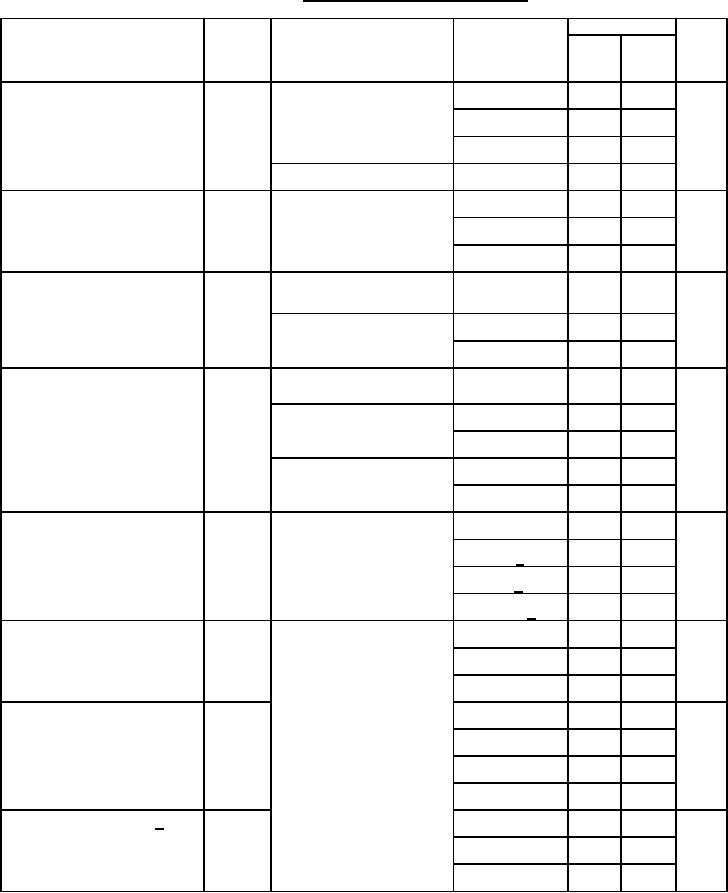
TABLE I. Electrical performance characteristics.
Units
Device
Limits
Test
Symbol
Conditions
Type
VSS = 0 V, VDD = 5.5 V
Min
Max
-55C ≤ TC ≤ +125C
unless otherwise specified
A
Quiescent supply current
IDD
VDD = 5.5 V
01, 02
50
or
03
200
ISS
04
250
VDD = 5.25 V
05, 06
-1000
Data retention supply voltage
PWR
Functional test
V
01, 02
2.0
DWN
03, 04
3.0
05, 06
2.5
TC = +25C
Operating current
IDDOP
mA
VDD = 5.5 V
01, 02, 03, 04
7
f = 1 MHz
TC = +25C
VDD = 5.25 V
05
4.5
f = 1 MHz
06
6
A
Data retention quiescent
ICCDR
VDD = 2 V IOUT = 0
01, 02
25
VIN = rail voltages
supply current
VDD = 3 V IOUT = 0
03
100
VIN = rail voltages
04
100
VDD = 2.5 V IOUT = 0
05
400
VIN = rail voltages
06
500
pF
Input capacitance
CI
VDD = 5.5 V
VIN = rail
01, 02
8
voltage
f = 1 MHz
03, 1/
8
04 1/
10
05, 06 1/
5
Address access time
tAVQV
See table III
ns
01, 02
120
03, 04
320
05, 06
250
Chip enable access time
tELQV
ns
01, 02
120
03, 04
300
05
280
06
280
Chip enable output time 1/
tELQX
ns
01, 02
5
03, 04
50
06
20
8
|
|
Privacy Statement - Press Release - Copyright Information. - Contact Us |