 |
|||
|
Page Title:
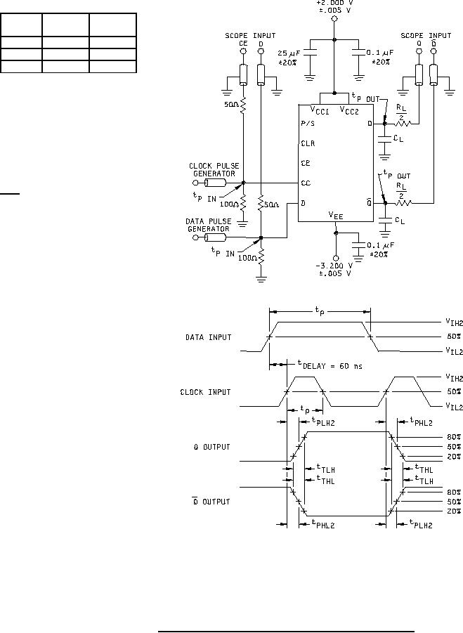
Figure 5. Synchronous switching test circuit for device types 01 and 02. |
|
||
| ||||||||||
|
|  MIL-M-38510/61C
GENERATOR CHARACTERISTICS
TC
VIH2
VIL2
10 mV
10 mV
25C
+1.11 V +0.31 V
125C
+1.24 V +0.36 V
-55C
+1.01 V +0.28 V
zOUT = 50Ω
tP (data) = 150 ns
tP (clocka) = 40 ns
PRR = 1 MHz
Device type 01
tTHL = 2.0 ns (20%-80%)
tTLH = 2.0 ns (20%-80%)
Device type 02
tTHL = 1.5 ns (20%-80%)
tTLH = 1.5 ns (20%-80%)
RL
2 = 50Ω 5%
SCOPE INPUT = 50Ω to GND
CL (test jig) ≤ 5 pF
NOTES:
1. Perform test in accordance with test table; each output is tested separately.
2. All input and output cables are equal lengths of 50 ohm coaxial cables. Wire length should be ≤ .250
(6.35 mm) from tp in to input pin and tp out to output pin.
3. Outputs not under test connected to a 100 ohm resistor to ground.
4. Note that observed pulse amplitude is attenuated by one half.
FIGURE 5. Synchronous switching test circuit for device types 01 and 02.
15
|
|
Privacy Statement - Press Release - Copyright Information. - Contact Us |
