 |
|||
|
Page Title:
Table 1. Electrical performance characteristics-cont. |
|
||
| ||||||||||
|
| 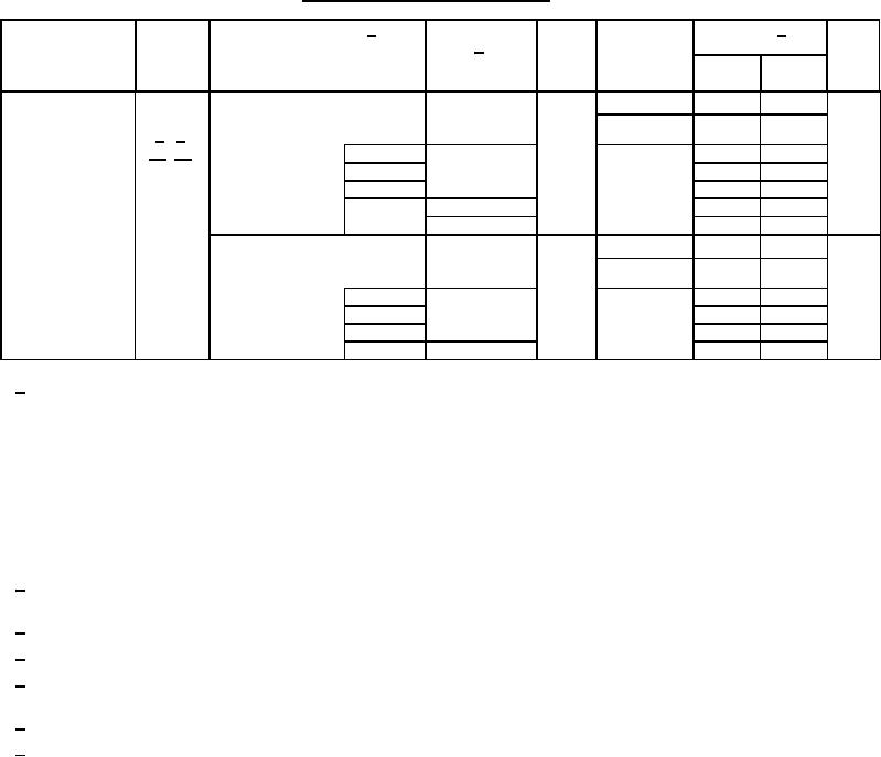 MIL-M-38510/757C
TABLE I. Electrical performance characteristics - Continued.
Unit
Test and
Test Conditions 1/
VCC
Group A
Limits 1/
Symbol
Device type
-55C ≤ TC ≤ +125C
MIL-STD-883
2/
subgroups
+3.0 V ≤ VCC ≤ +5.5 V
test method
Min
Max
unless otherwise specified
3.0 V
ns
Propagation
tPLZ,
CL = 50 pF minimum,
9, 11
1.0
11.5
03-05
RL = 500Ω
delay time,
tPHZ
10, 11
10
1.0
13.0
4/ 5/
output disable
see figure 4
15/ 16/
3003
M
9
1.0
11.5
03-05, 11
D
1.0
11.5
P, L, R
1.0
11.5
F
05
1.0
13.5
03
1.0
11.5
ns
4.5 V
CL = 50 pF minimum,
9, 11
1.0
9.0
03-05
RL = 500Ω
10, 11
10
1.0
10.5
see figure 4
9
M
1.0
9.0
03-05, 11
D
1.0
9.0
P, L, R
1.0
9.0
1.0
9.0
F
03, 05
1/ Each input/output, as applicable shall be tested at the specified temperature for the specified limits. Output terminals not
designated shall be high level logic, low level logic, or open, except as follows:
a. VIC (pos) tests, the GND terminal can be open. TC = +25C.
b. VIC (neg) tests, the VCC terminal shall be open. TC = +25C.
c. All ICC tests, the output terminal shall be open. When performing these tests, the current meter shall be
placed in the circuit such that all current flows through the meter.
For negative and positive voltage and current values, the sign designates the potential difference in reference to GND and
the direction of current flow respectively and the absolute value of the magnitude, not the sign, is relative to the minimum and
maximum limits, as applicable, listed herein.
2/ The word "All" in the device type column means non-RHA limits for all device types. M, D, P, L, R, and F in the conditions
column specify the postirradiation limits for those device types specified in the device type column.
3/ This test is guaranteed, if not tested, to the limits specified in table I.
4/ RHA samples do not have to be tested at -55C and +125C prior to irradiation.
5/ When performing postirradiation electrical measurements for RHA level, TA = +25C. Limits shown are guaranteed at
TA = +25C 5C.
6/ Transmission driving tests are performed at VCC = 5.5 V dc with a 2 ms duration maximum.
7/ Three-state output conditions are required. For IOZL, set outputs to high state. For IOZH, set outputs to low state. Set output
enable control pins to VIL = VIL(MAX) and VIH = VIH(MIN), as required.
13
|
|
Privacy Statement - Press Release - Copyright Information. - Contact Us |
